34 | Section 5
hole located below capacitor C137.
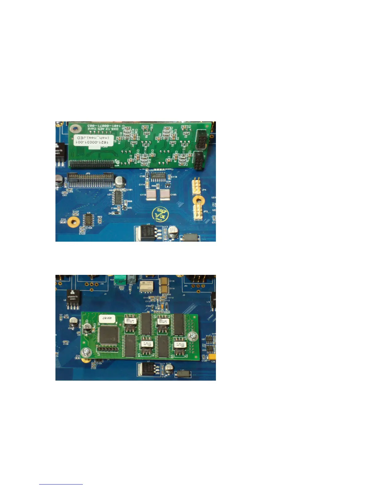
5. Align connectors JR2 and JR1 on the AES plug-in module with JP4 and JP3 on the
motherboard. Likewise, align connector JP1 on the plug-in module with JP5 on the
motherboard. (See gure below). Push rmly to seat the plug-in module onto the moth-
erboard. Visually conrm that connector JR2 ts onto all four sets of pins on JP4, and
JR1 connector ts onto all four sets of pins on JP3.
6. Take the two mounting screws from the kit (1301-00077-100) and install them into the
female side of the board standos in order to secure the AES I/O module to the hybrid
motherboard.
7. Reinstall the top cover using the 10 Phillips screws.
8. Plug the AC power cord back into the socket and wait for the unit to power up. e hybrid
unit will automatically detect the presence of the AES plug-in module, and directly trans-
mit and receive digital data at the clock rate of the AES source plugged into the SEND IN
XLR input connector.
9. You can use the built-in diagnostic mode of the hybrid unit to conrm that the AES I/O
module is working properly. Refer to Section 6 of the User’s Manual for instructions on
how to enter this mode of operation. Test “T2” is a loopback test that takes audio present