bank are set to the OFF position for Factor Default setting, thus no LEDs are lit on the EQ
LO meter).
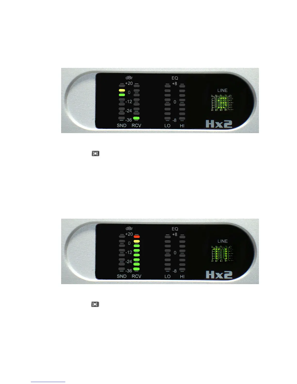
6.1.3 T1 Test - 400 Hz Tone Generation
Press the hybrid button to advance to the next diagnostic test. e Line Status display
should indicate ‘T1’. e DSP chip on the motherboard generates a 400 sine wave that is sent
to the RCV OUT XLR connector for each hybrid. e output level of the sine wave at the XLR
is +20 dBu, and the output level should be displayed on the RCV meter bargraph. (See gure
below).
e diagnostic test also takes the telephone line o-hook and outputs a –7 dBm, 400 Hz sine
wave. A telephone line or line simulator must be plugged into the LINE RJ11 jack to activate
the telephone interface circuitry on the hybrid motherboard. e 400 Hz tone will also be
audible on the PHONE RJ11 jack, but it will be heard mixed in with the telco’s dial-tone or
re-order tone.
6.1.4 T2 Test - Studio Loopback
Press the hybrid button to advance to the next diagnostic test. e Line Status display
should indicate ‘T2’. is test simply takes audio present on the SEND IN XLR connector
and loops it back to the RCV OUT XLR connector without any processing. e loopback test
works with either analog or AES inputs.
is diagnostic test can be used to adjust the INPUT LEVEL pot located in the back of the
hybrid chassis. Connect a +4 dBu signal and adjust the INPUT LEVEL pot until the yellow
LED segment illuminates. (See gure below).
38 | Section 6