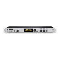
AES I/O OPTION | 35
at the SEND IN XLR connector and loops it back to the RCV OUT XLR connector
unprocessed. e input signal and output signal levels are also displayed on the Front
Panel SND and RCV LED bar graph meters.
5.2 AES Channel Assignment
e studio input signal should be on the LEFT AES channel feeding the SEND IN XLR
connector. e studio output signal is present on the LEFT AES channel on the RCV OUT
XLR connector.
When the two hybrids are operating independently (internal mix-minus mode is disabled), the
separate studio input signals should be on the LEFT AES channel being fed into the respective
SEND IN #1 and SEND IN #2 XLR connectors. e studio output signals will be brought
out separately on the LEFT AES channel on the respective RCV OUT #1 and RCV OUT #2
XLR connectors.
When the internal mix-minus mode is enabled on the Hx2 hybrid unit, only the LEFT AES
channel being fed into SEND IN #1 is used as the studio input signal to BOTH hybrids. e
studio output signals are brought out separately on the LEFT AES channel on the respective
RCV OUT #1 and RCV OUT #2 XLR connectors.
5.3 Restoring an AES equipped unit to analog operation
1. With power removed, remove the unit cover and the two mounting screws that fasten the
AES daughter board to the main board.
2. Remove and store the AES daughter board.
3. Install 2 sets of four jumpers each on JP3 and JP4 locations on the main board. Analog
audio will now be present on the rear panel XLR connectors.
4. Replace cover and verify proper operation.
 Loading...