| 33
5
AES I/O OPTION
5.1 Installation Instructions
e Hx1 and Hx2 hybrid units can be purchased with the optional AES I/O module pre-
installed, or as an upgrade kit to be installed in the eld. e AES board Upgrade Kit [2011-
00068] includes the following items:
1701-00149-100 (Qty =1) AES Board assembly
1308-00023-100 (Qty =2) board stando, M3x10mm, MF
1301-00077-100 (Qty =2) screw, M3x6mm Phillips Pan-Head steel zinc
e following instructions explain the steps to install the AES I/O module onto the mother-
board using the upgrade kit. Chassis cover removal and upgrade kit installation should only
be performed by a qualied technician or engineer.
1. AC power must be disconnected prior to removing the chassis cover. Remove the AC
power cable from the power inlet in the back of the hybrid unit.
2. Remove the 10 Phillips screws that mount the top cover to the hybrid chassis.
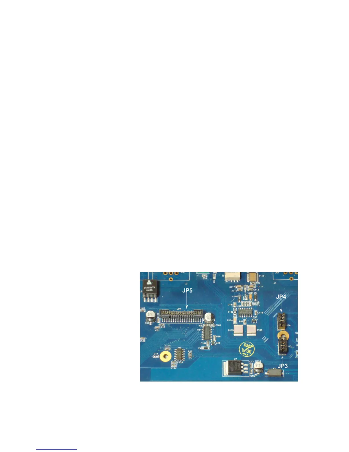
3. Locate the two sets of four jumpers each at both JP3 and JP4 on the motherboard.
Likewise, locate edge connector JP5 on the motherboard. (See gure below). Remove
the jumpers from both JP3 and JP4 and reserve them for future use if you like. (ese
jumpers must be re-installed if the AES I/O module is removed and the Hx is converted
back to analog operation).
4. Locate the two gold plated mounting holes shown in the gure. Take one of the board
standos (1308-00023-100) and screw the male end into the mounting hole located
between JP3 and JP4. Take the other stando and screw the male end into the mounting