Section 3 - Step-By-Step Assembly 29
Temp-Cast 2000 Installation Manual
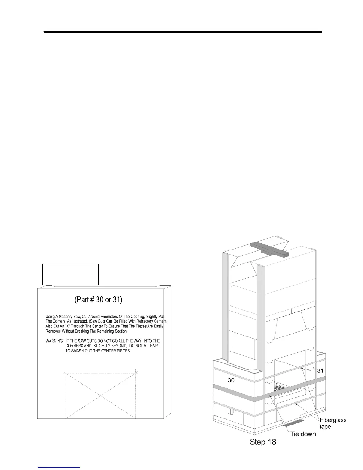
STEP 18:
If the flue connection is on the side of the fireplace, the hole for the flue connector is cut at this
point, as shown. (See below for important suggested cutting technique.) (Refer also to Fig. #3 &
#4.) (For a Corner Fireplace, see page 31, for Steps 18 to 20.)
Dry assemble the lower heat exchange channels, #30 & 31, and mark the location of the flue
hole. The hole in the heat exchange channel should be cut as tightly as possible, up to about 1/4"
larger all around than the flue tile.
In addition, cut a 6" x 6" hole in the opposite heat exchange channel, on the non-chimney side,
for a soot cleanout door. Align this hole with the centre of the cross manifold, part # 3. (If a
rear chimney connection has been made, the second soot door may be installed on the opposite
side channel, to simplify inspection and cleaning from both sides. Both soot doors should align
with the centre of the cross manifold. A third cleanout door will be needed for the base of the
chimney.)
The transition from fireplace to flue connector should be as smooth and rounded as possible, so
that the smoke does not encounter any corners or ledges as it enters the flue connector. (Refer to
Fig. 8.)
Ensure that the ceramic fibre strips have been applied to the core walls. Now position the first 2
heat exchange channels, using refractory mortar on their bottom edges only.
Use a “tie-down” or web clamp around the 2 channels to slightly
compress the ceramic fibre. Secure the channels with 2 bands of
packing tape, then remove the tie-down.
Weights
#30 & 31 - 95 lbs