- 3 -
BMS
RS GND
RSA
RSB
18
ENG
c.pCO sistema +0300057EN rel. 1.1 - 13.04.2015
J3 Disp
+Vterm
LH
J4 FBus J5 CAN
J3 Disp
J4 FBus
J6 BMS
+Vterm
J3 Disp
J4 FBus
J6 BMS
+Vterm
G
G0
G
G0
G
G0
24 Vac
L
N
230 Vac
24 Vac
L
N
J25 BMS2 J26 FBus2
J11 pLAN
c.pCO
G
G0
J25 BMS2
J26 FBus2
J11 pLAN
c.pCO
G
G0
J25 BMS2J26 FBus2
J11 pLAN
c.pCO
G
G0
Fig. 4.e
The procedure for earthing the shield is described in the corresponding
paragraph.
Case 2: multiple boards connected to a Master/Slave network powered
by diff erent transformers (with G0 not earthed); this is a typical application
of multiple boards inside diff erent electrical panels. If the network is more
than 100 m long, the 120 Ω, ¼ W terminating resistor is required.
J3 Disp
+Vterm
LH
J4 FBus J5 CAN
J3 Disp
J4 FBus
J6 BMS
+Vterm
J3 Disp
J4 FBus
J6 BMS
+Vterm
G
G0
G
G0
G
G0
230 Vac
24 Vac
L
N
230 Vac
24 Vac
L
N
230 Vac
24 Vac
L
N
R = 120 Ω
R = 120 Ω
J25 BMS2 J26 FBus2
J11 pLAN
c.pCO
G
G0
J25 BMS2
J26 FBus2
J11 pLAN
c.pCO
G
G0
J25 BMS2 J26 FBus2
J11 pLAN
c.pCO
G
G0
230 Vac
24 Vac
L
N
230 Vac
24 Vac
L
N
230 Vac
24 Vac
L
N
R = 120 Ω
R = 120 Ω
Fig. 4.f
Important: the earth connection (if any) should be made only on
one point of the earth line (same earthing terminal for all controllers).
The procedure for earthing the shield is described in the corresponding
paragraph.
Optically-isolated serial port
This is the case of serial ONE - BMS1, serial TWO - Fieldbus 1 and the built-
in ports serials THREE and FOUR on optically-isolated models. Regardless
of the type of power supply or earthing, use a 3-wire shielded cable
connected as shown in the fi gure. If the network is more than 100 m
long, the terminating resistor is required.
J25 BMS2 J26 FBus2
J11 pLAN
c.pCO
G
G0
J25 BMS2
J26 FBus2
J11 pLAN
c.pCO
G
G0
J25 BMS2 J26 FBus2
J11 pLAN
c.pCO
G
G0
R = 120 Ω
R = 120 Ω
Power
supply
Fig. 4.g
The procedure for earthing the shield is described in the corresponding
paragraph.
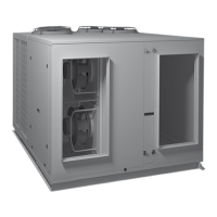
Procedure for earthing the shield
The shield of the serial cable is earthed diff erently according to the
length, as shown in the fi gure (where A=FBus terminal, B=BMS terminal).
Case 1: distance between controllers less than 0.3 m: earth only one end
of the cable.
L < 300 mm
L < 300 mm
AB B
Fig. 4.h
Case 2: distance between controllers greater than 0.3 m: two possibilities.
- earth one end with a bridge between the shields
L >300 mm
L > 300 mm
AB B
Fig. 4.i
- earth both ends of the cable (no bridge between shields).
L >300 mm
L > 300 mm
AB B
Fig. 4.j
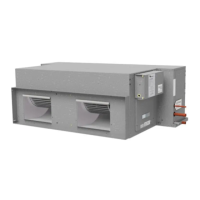
Multipleunitsusinganetworkswitch:
4.5 BMS – Modbus Connection
Connect to supplied terminals in electrical box; refer
Specications document for wiring detail, sheet 2 grid
reference D0, reproduced below.
Figure 1: RS485 terminal block in electrical box
Figure 2: Carel recommendations for shield grounding
4.6 Stand Alone
Option 1:
1. Install optional Carel pGD1 remote display (Item no.
201-000-379) inside building, connection to Carel
c.pCO master controller J10 port. Cable RJ11.
2. Connect Room temperature and humidity sensor
directly to Carel c.pCO master controller. See
Specication sheet for wiring schematic/sheet 2 for
wiring details of Room temperature input) and Room
RH%.
Option 2:
In absence of a Carel remote pGD1 the unit can be
controlled using the on-board Carelc.pCO master controller
with its included digital display.
4.7 Remote on/off
The unit’s UC8 Controller has an input for a remote on/
off function on terminal ‘On’, signal return is terminal ‘0V’.
When used the remote on/off terminals should connect to a
voltage-free relay contact. When not used the remote on/off
terminals should be shorted (‘looped’).
4.8 Economiser Wiring
See Specications document for wiring schematic/
sheet 1, lower left corner.
UC8 Master-Slave Connection
5. ECONOMISER OPTION
The Economiser package that is factory tted consists of
two opposed blade dampers, one for the fresh air and the
other for the return air. They come complete with individual
damper motors controlled using a 0–10V dc signal. The
package also includes a weatherhood assembly that is
usually supplied as a separate item for tting on site. It is
important that the installation instructions for the tting of
the weatherhood are followed otherwise it is possible some
water ingress from rain could occur.
If the outdoor temperature as well as the enthalpy is below
that of the return air, the fresh air damper can be opened
and the return air damper closed to provide the rst stage of
cooling.
The air damper’s minimum and maximum openings can
be adjusted using the Master Controller (c.PCO) Menu/
Settings/Damper Cong. Each of the dampers can have
settings for use in both the occupied and unoccupied
modes. The settings for opening based on an optional CO
2
air quality sensor can also be adjusted. Many installations
may require a minimum fresh air introduction of 10–15%
(refer local Building Code regulations) and the stop may be
set on site to facilitate this. Ensure the air ow entering the
unit is equal between full return air and full Economiser by
adjusting the damper stops on both Return and Fresh
air dampers.
6. START-UP PROCEDURE
6.1 Before starting the compressors
1. Before working on the unit isolate mains power.
2. Remove the shipping wedges from beneath each
compressor. Check that each compressor is securely
mounted.
3. Check oil level as per label attached to each
compressor.
4. Check the mains power and controls wiring are correct.
5. Check tightness of all electrical connections.
6. Check the air lters have been correctly installed.
7. Check that all indoor fan motors can freely rotate.
8. Check the supply voltage between each phase and
neutral.
9. Check air diffusers and ductwork are open.
10. Apply mains power to the unit by closing the mains
isolating switch.
11. Before starting the compressors a four hour delay
period is required to allow the crankcase heaters to
drive any liquid refrigerant out of the compressor oil.
Mains power must be switched on during this four hour
delay period.
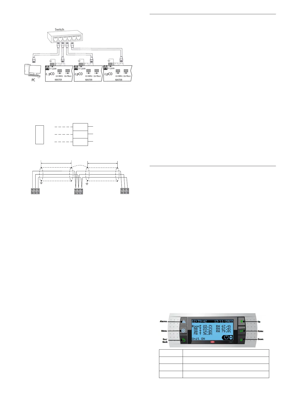
6.2 Master Controller Display (Carelc.pCO)
Button Function
Alarm System Alarm indication and Reset
Menu Go to Main menu
Esc Return to previous page or Exit menu
 Loading...