24
c. SYSTEM OVERVIEW
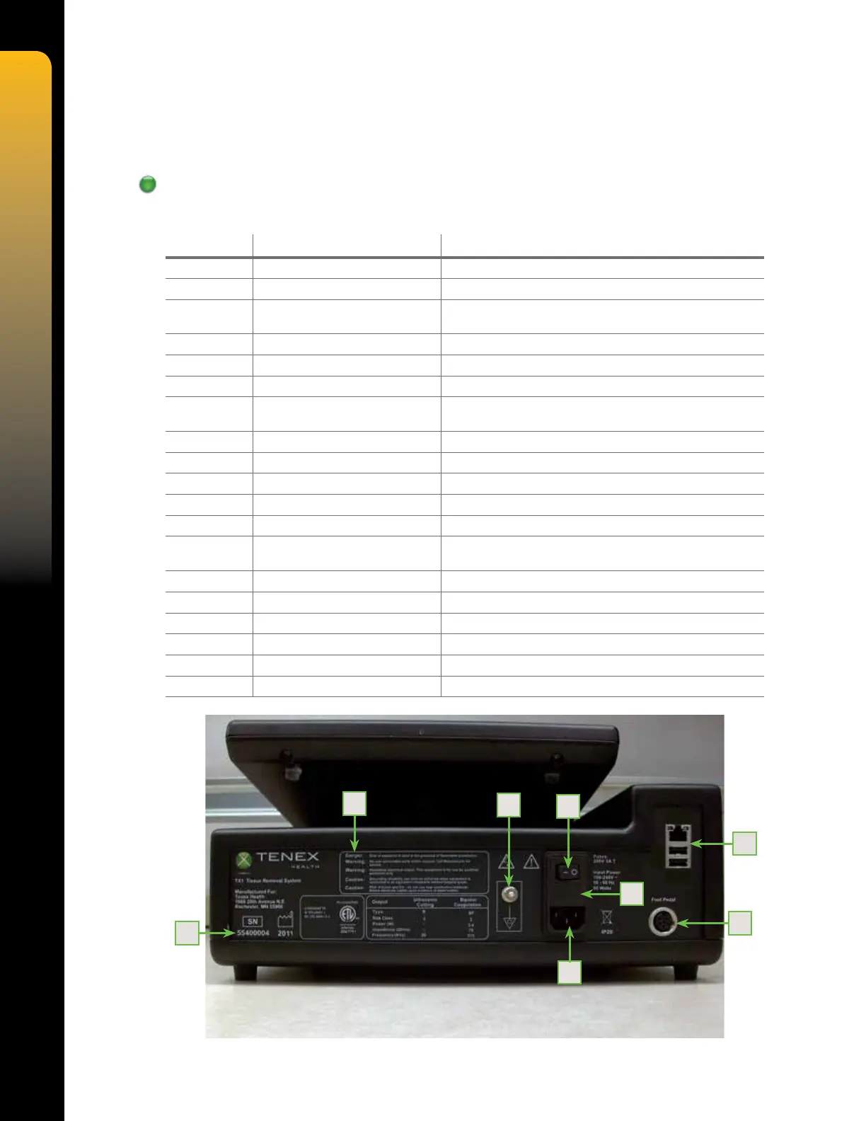
FIgures 9, 10, and 11 refer to all controls, indicators, and connectors on the TX Console. The
associated table 3 describes these in detail.
Console Overview
Table 3. Controls, Indicators, and Connections
NUMBER NAME DESCRIPTION
1 REAR PANEL LABEL Displays system ratings, serial number, warnings and cautions
2 ON/OFF SWITCH "I" is ON and "O" is OFF
3 EQUIPOTENTIAL GROUND
STUD
Provides a means of securely linking the earth grounds of the
Console to other grounded equipment
4 FUSE HOLDER Holds system fuses
5 ETHERNET/USB PORTS Factory use
6 FOOT PEDAL CONNECTOR Connection for system foot pedal
7 AC POWER INPUT Provides power connection and overload protection to
the system
8 SERIAL NUMBER Unique code assigned for identication of the unit
9 CARTRIDGE LOCK Locking mechanism for tube set cartridge
10 VACUUM SENSOR Sensor for measuring vacuum
11 CARTRIDGE RELEASE BUTTON Releases the tube set cartridge when pressed
12 CUT CONNECTOR Provides power to cutting TX MicroTip
13 COAGULATION CONNECTOR Provides power to the coagulation handpiece (user-provided
accesory)
14 AIR CONNECTOR Provides pressurized air to irrigation cuff
15 IRRIGATION VALVE Controls ow of irrigation uid
16 VENT VALVE Controls aspiration line venting
17 PERISTALTIC PUMP HEAD Provides system aspiration
18 TOUCHSCREEN DISPLAY Provides access to user interface
19 SPEAKERS Provide audible feedback
Figure 9 – Rear View
1
3
2
4
5
6
7
8