

A
angel88Jul 27, 2025
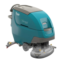
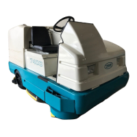
Why is my Tennant Floor Machine leaving water behind?
- RrobinsonantonioJul 27, 2025
If your Tennant Floor Machine leaves water behind, it could be due to several reasons. The rear squeegee blades might be worn and need rotating or replacing, or the rear squeegee may be out of adjustment. Worn or misadjusted side squeegees can also cause this. Other potential causes include excessive solution flow (reduce the flow), a clogged vacuum hose (flush it), a full recovery tank (drain it), a stuck float (clean it), debris on the rear squeegee (remove it), foam in the recovery tank (empty the tank and use less detergent), or a disconnected/damaged vacuum hose (reconnect or replace it). A damaged vacuum fan to recovery tank hose should be replaced.