47
SBAU171D–May 2010–Revised January 2016
Submit Documentation Feedback
Copyright © 2010–2016, Texas Instruments Incorporated
External Optional Hardware
Appendix B
SBAU171D–May 2010–Revised January 2016
External Optional Hardware
B.1 Optional External Hardware (Not Included)
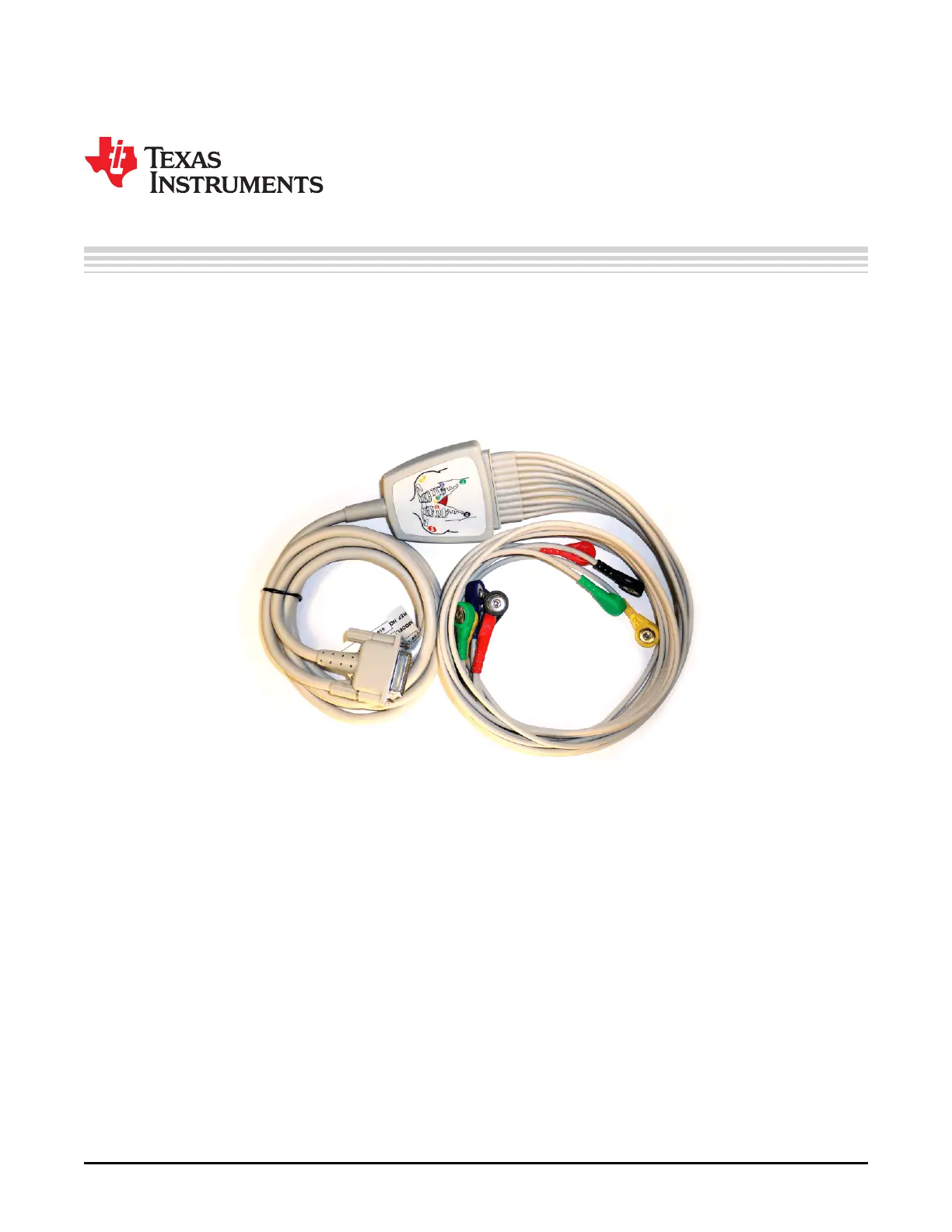
The input of the ADS1x98ECG-FE requires a DB15 connector. Figure 45 illustrates the most optimal cable
connection to the ADS1298ECG-FE. Figure 46 and Figure 47 show two alternate ways that cables can be
constructed to interface with the ADS1x98ECG-FE. Figure 48 shows an alternate testing tool to the
instrument used in the tests for this user guide (refer to Section 5.7.1).
Figure 45. 15-Pin, Shielded Connector from Biometric Cables
 Loading...


