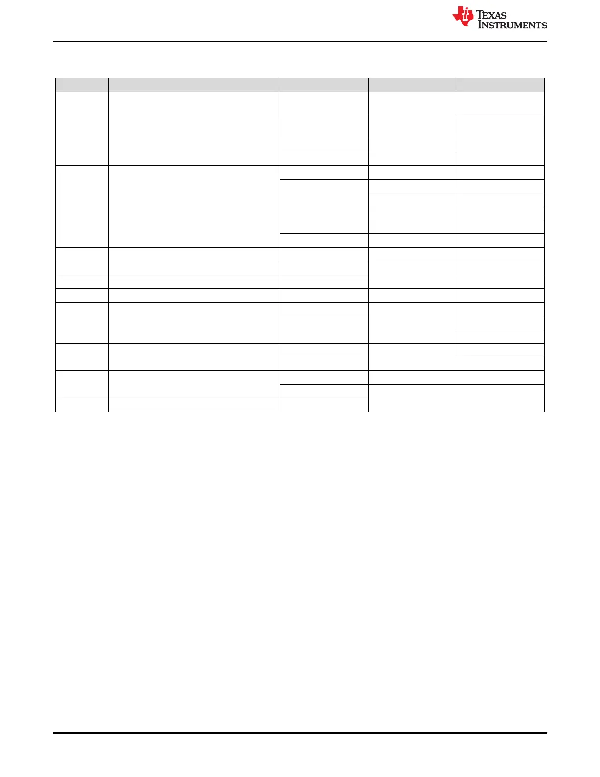
The SoC has different IO groups. Each IO group is powered by specific power supplies as shown in Table 3-6.
Table 3-6. SoC Power Supply
SI.No. Power Supply SoC Supply Rails IO Power Group Power
1 VDDA_CORE VDDA_0P85_SERDES
0
SERDES0 0.85
VDDA_0P85_SERDES
0_C
0.85
VDDA_0P85_USB0 USB0 0.85
VDD_MMC0 MMC0 0.85
2 SoC_DVDD3V3 VDDS_MCU MCU 3.3
VDDA_3P3_USB0 USB0 3.3
VDDSHV0 General 3.3
VDDSHV1 PRG0 3.3
VDDSHV2 PRG1 3.3
VDDSHV3 GPMC 3.3
3 VDDA_1V8_MCU VDDA_MCU MCU 1.8
4 VDDA_MCU_ADC VDDA_ADC ADC0 1.8
5 VDDA_1V8_SERDES VDDA_1P8_SERDES0 SERDES0 1.8
6 VDDA_1V8_USB0 VDDA_1P8_USB0 USB0 1.8
7 VDDA_1V8 VDDS_OSC OSC0 1.8
VDDA_TEMP_0/1 1.8
VDDA_PLL_0/1/2 1.8
8 VDD_DDR4 VDDS_DDR DDR0 1.2
VDDS_DDR_C 1.2
9 SOC_DVDD1V8 VDDSHV4 FLASH 1.8
VDDS_MMC0 MMC0 1.8
10 VDDSHV_SD_IO VDDSHV5 MMC1 1.8
3.4.4 Configuration
3.4.4.1 Boot Modes
The boot mode for the EVM is defined by either a bank of switches SW2 and SW3 or by the I2C buffer (U96)
connected to the test automation connector (J38). All the boot mode pins have a weak pull-down resistor and a
switch capable of connecting to a strong pull up resistor. Switch set to “ON” corresponds to logic “HIGH” while
“OFF” corresponds to logic “LOW”.
For a full description of all AM64x SoC supported bootmodes, see the AM64x Sitara™ Processors Data Manual
and AM64x Processors Silicon Revision 1.0 Texas Instruments Families of Products Technical Reference
Manual.
The following boot modes are supported by EVM (and subject to change):
1. OSPI
2. MMC1 - SD Card
3. MMC0 - eMMC installed
4. USB - boot using host mode with bulk storage. USB 2.0 mass storage using FAT16/32 (thumb drive)
5. USB - device boot DFU
6. UART
7. No-Boot
System Description
www.ti.com
18 AM64x/AM243x GP EVM User's Guide SPRUIX0C – FEBRUARY 2021 – REVISED JUNE 2021
Submit Document Feedback
Copyright © 2021 Texas Instruments Incorporated

 Loading...


