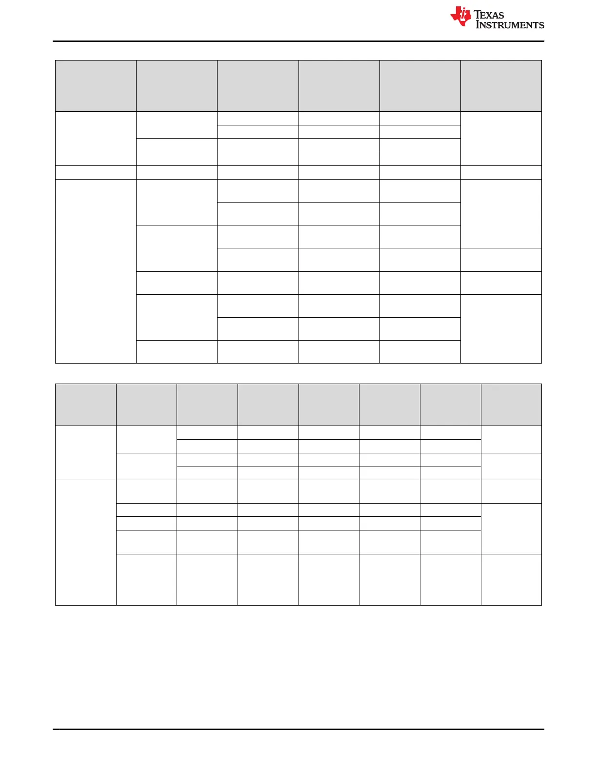
Table 3-19. Default Strap Setting of CPSW Ethernet PHY
Strap Setting Pin Name Strap Function
Mode for
PRG0_PRU1,
PRG0_PRU0
,PRG1_PRU1,
PRG1_PRU0
Value of Strap
Function for PRG0
and PRG1 Description
PHY Address RX_D2 PHY_AD3 1 0 PHY Address: 0000
PHY_AD2 1 0
RX_D0 PHY_AD1 1 0
PHY_AD0 1 0
Auto Negotiation RX_DV/RX_CTRL Auto-neg 3 0 Auto neg Disable=0
Modes of Operation LED_2 RGMII Clock Skew
TX[1]
1 0 RGMII TX Clock
Skew is set to 2 ns
RGMII Clock Skew
TX[0]
1 0
LED_1 RGMII Clock Skew
TX[2]
1 0
ANEG_SEL 1 0 advertise ability of
10/100/1000
LED_0 Mirror Enable 1 0 Mirror Enable
Disabled
GPIO_1 RGMII Clock Skew
RX[2]
1 0 RGMII RX Clock
Skew is set to 2 ns
RGMII clock Skew
TX[1]
1 0
GPIO_0 RGMII clock Skew
RX[0]
1 0
Table 3-20. Default Strap Setting of ICSSG Ethernet PHYs
Strap Setting Pin Name Strap Function
Mode for
PRG1_RGMII2
(ICSSG1)
Value of Strap
Function for
PRG1_RGMII2
(ICSSG1)
Mode for
PRG1_RGMII1
(ICSSG2)
Value of Strap
Function for
PRG1_RGMII1
(ICSSG2) Description
PHY Address RX_D1 PHY_AD3 3 1 3 1 ICSSG1 PHY
Address: 00011
PHY_AD2 3 1 3 1
RX_D0 PHY_AD1 0 0 3 1 ICSSG2PHY
Address: 01111
PHY_AD0 0 0 3 1
Modes of
Operation
RX_CNTL Mirror Enable 0 0 0 0 Mirror Enable
Disabled
LED_2 ANEGSEL_1 0 0 0 0 Auto-
negotiation,
10/100/1000
advertised,
Auto-MDI-X
LED_1 ANEGSEL_0 0 0 0 0
LED_0 ANEG_DIS 0 0 0 0
JTAG_TDO/
GPIO_1
OPMODE_0 0 0 0 0 RGMII to
Copper
(1000BaseT/
100Base-TX/
10Base-Te)
The PHY devices include integrated MDI termination resistors, so external termination is not provided.
Interrupt: The interrupt from two ICSSG PHYs from PRG1 domain are tied together and is connected to
EXTINTN pin of the AM64x/AM243x. An option for connecting the interrupt from CPSW PHY to the PRG1
ICSSG Interrupt pins is also provided.
Three configurable LED pins and a GPIO of Ethernet PHY are used to indicate link status. Several functions can
be multiplexed onto the LEDs for different modes of operation. The LED operation mode can be selected using
System Description
www.ti.com
36 AM64x/AM243x GP EVM User's Guide SPRUIX0C – FEBRUARY 2021 – REVISED JUNE 2021
Submit Document Feedback
Copyright © 2021 Texas Instruments Incorporated

 Loading...


