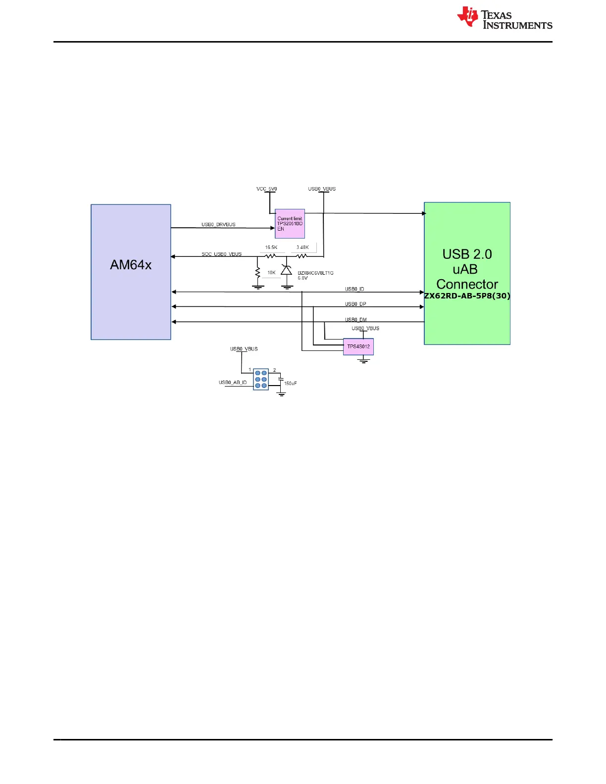
3.4.11 USB 2.0 Interface
The USB0 port of AM64x/AM243x is used for USB 2.0 interface. The USB signals are terminated to a uAB
connector and supporting circuitry is included to allow the USB interface to be configured as either host or a
self-powered slave device.
In the host mode, up to 500 mA, 5 V is supported for the slave device. A power switch is included that is
controlled by DRV_VBUS signal from the AM64x/AM243x.
A 2x3 header (J23) is provided to install the 2-position ganged shunt to configure the port for host mode as
shown in Figure 3-24. Place the shunt on pin no. 1 and 2 to enable bulk capacitance on VBUS and place the
shunt on pin 5 and 6 to connect ID pin to ground.
Figure 3-24. AM64x/AM243x USB 2.0 Host Interface
3.4.12 PCIe Interface
The Serdes0 interface of AM64x/AM243x is used to implement a x1 lane PCIe interface with the signals routed
to a x4 PCIe slot connector. PCIE-064-02-F-D-TH connector from Samtec is be used for the PCIe interface
and this connector meets the PCIe CEM v2.0 specification both physically and electrically and it is designed to
support a 25W slot including 2.1A for the 12 V rail and 3A for the 3.3 V rail. The PCIe interface is designed
to support either root complex operation or endpoint operation with a cross over cable. SoC_I2C1 is used for
control purpose. The link activation signal from PCIe connectors is pulled up to VCC3V3_SYS.
Clock: SERDES REFCLK is routed to the PCIe REF CLK pins to allow either receiving or providing a clock from
the connector (no separate PLL to generate PCIe REF CLK available on the EVM).
Hot plug: The PRSNT1# and PRSNT2# signals are the hot plug presence detect signals. The PRSNT2# is
pulled up and PRSNT1# is connected to ground so that PRSNT2# will be pulled low when a daughter card is
plugged in. A 3 pin header (J35) is provided to choose between RC and EP mode.
Reset: A 3 pin header (J34) is provided to select the reset source for host and endpoint PCIe operation. In case
of host mode, PCIe_RST_OUT signal from IO Expander and RESETSTATz signal from SoC are ANDed and the
output is connected to PCIe connector through 3 pin header. A jumper is mounted for the connectivity. Whereas
in case of PCIe end point operation, the AM64x SoC receives reset signal from the add-on card and passed on
to the MCU_PORz pin. The reset signal is connected to 3 pin header and the selection should be made with a
jumper.
The PCIe x4 Connector JTAG signals are unused and test points are provided on the signals.
System Description
www.ti.com
44 AM64x/AM243x GP EVM User's Guide SPRUIX0C – FEBRUARY 2021 – REVISED JUNE 2021
Submit Document Feedback
Copyright © 2021 Texas Instruments Incorporated

 Loading...


