9.3.5 Power Management
The TPS65982 Power Management block receives power and generates voltages to provide power to the
TPS65982 internal circuitry. These generated power rails are LDO_3V3, LDO_1V8A, and LDO_1V8D. LDO_3V3
is also a low power output to load flash memory. VOUT_3V3 is a low power output that does not power internal
circuitry that is controlled by application code and can be used to power other ICs in some applications. The
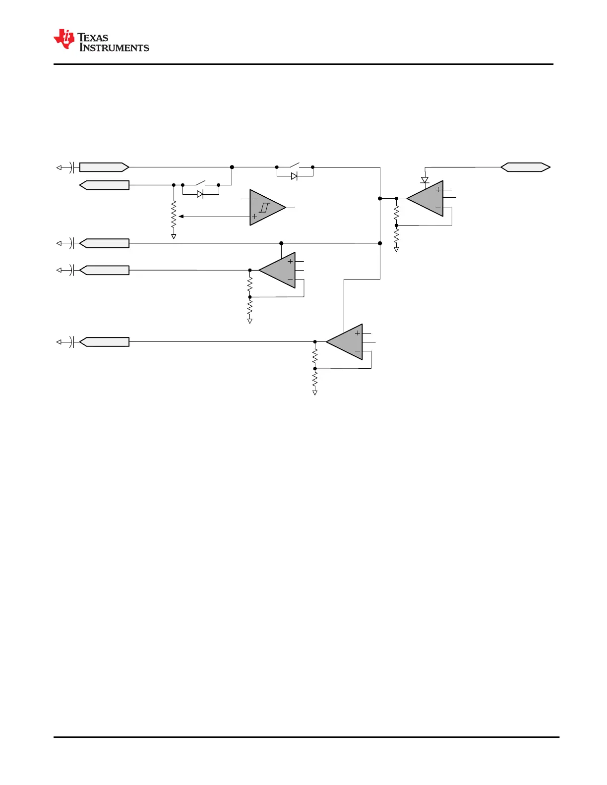
power supply path is shown in Figure 9-40.
LDO
LDO_1V8D
EN
LDO_3V3_VB_EN
LDO
VREF
S2
S1
Digitally
adjustable
trip Point
VREF
EN
LDO_1V8D_EN
LDO
VREF
LDO_1V8A
VBUS
EN
LDO_1V8A_EN
VREF
VIN_3V3
VOUT_3V3
LDO_3V3
To Digital Core
Figure 9-40. Power Supply Path
The TPS65982 is powered from either VIN_3V3 or VBUS. The normal power supply input is VIN_3V3. In this
mode, current flows from VIN_3V3 to LDO_3V3 to power the core 3.3 V circuitry and the 3.3 V I/Os. A second
LDO steps the voltage down from LDO_3V3 to LDO_1V8D and LDO_1V8A to power the 1.8 V core digital
circuitry and 1.8 V analog circuits. When VIN_3V3 power is unavailable and power is available on the VBUS,
the TPS65982 will be powered from VBUS. In this mode, the voltage on VBUS is stepped down through an
LDO to LDO_3V3. Switch S1 in Figure 9-40 is unidirectional and no current will flow from LDO_3V3 to VIN_3V3
or VOUT_3V3. When VIN_3V3 is unavailable, this is an indicator that there is a dead-battery or no-battery
condition.
9.3.5.1 Power-On and Supervisory Functions
A power-on-reset (POR) circuit monitors each supply. This POR allows active circuitry to turn on only when a
good supply is present. In addition to the POR and supervisory circuits for the internal supplies, a separate
programmable voltage supervisor monitors the VOUT_3V3 voltage.
9.3.5.2 Supply Switch-Over
VIN_3V3 takes precedence over VBUS, meaning that when both supply voltages are present the TPS65982
will power from VIN_3V3. Refer to The Figure 9-40 for a diagram showing the power supply path block. There
are two cases in with a power supply switch-over will occur. The first is when VBUS is present first and then
VIN_3V3 becomes available. In this case, the supply will automatically switch-over to VIN_3V3 and brown-out
prevention is verified by design. The other way a supply switch-over will occur is when both supplies are present
and VIN_3V3 is removed and falls below 2.85 V. In this case, a hard reset of the TPS65982 occurs prompting a
re-boot.
9.3.5.3 RESETZ and MRESET
The VIN_3V3 voltage is connected to the VOUT_3V3 output by a single FET switch (S2 in Figure 9-40).
www.ti.com
TPS65982
SLVSD02E – MARCH 2015 – REVISED AUGUST 2021
Copyright © 2021 Texas Instruments Incorporated
Submit Document Feedback
59
Product Folder Links: TPS65982