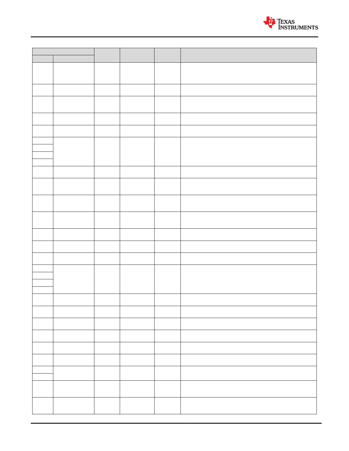
Table 6-1. Pin Functions (continued)
PIN
TYPE CATEGORY POR STATE DESCRIPTION
NO. NAME
F10
BUSPOWERZ
(GPIO10)
Analog Input
Digital core I/O
and control pins
Input (Hi-Z)
General purpose digital I/O 10. Sampled by ADC at boot. Tie pin to
LDO_3V3 through a 100-kΩ resistor to disable PP_HV and PP_EXT
power paths during dead-battery or no-battery boot conditions. Refer to
the BUSPOWERZ table for more details.
F11
RESETZ
(GPIO9)
Digital I/O
Digital core I/O
and control pins
Push-pull
output (Low)
General purpose digital I/O 9. Active-low reset output when VOUT_3V3 is
low (driven low on start-up). Float pin when unused.
F2 UART_RX Digital input
Port multiplexer
pins
Digital input
UART serial receive data. Connect pin to another TPS65982 UART_TX to
share firmware. Connect UART_RX to UART_TX when not connected to
another TPS65982 and ground pin through a 100-kΩ resistance.
F3 No Ball Blank
Ground and no
connect pins
— Unpopulated ball for A1 marker and unpopulated inner ring.
F4 SWD_DATA Digital I/O
Port multiplexer
pins
Resistive pull
high
SWD serial data. Float pin when unused.
F5
GND Ground
Ground and no
connect pins
— Ground. Connect all balls to ground plane.
F6
F7
F8
F9 No Ball Blank
Ground and no
connect pins
— Unpopulated ball for A1 marker and unpopulated inner ring.
G1 LDO_3V3 Power
Low-current
power pins
—
Output of the VBUS to 3.3-V LDO or connected to VIN_3V3 by a switch.
Main internal supply rail. Used to power external flash memory. Bypass with
capacitance CLDO_3V3 to GND.
G10 GPIO6 Digital I/O
Digital core I/O
and control pins
Hi-Z
General purpose digital I/O 6. Float pin if it is configured as a push-pull
output in the application. Ground pin with a 1-MΩ resistor when unused in
the application.
G11 GPIO3 Digital I/O
Digital core I/O
and control pins
Hi-Z
General purpose digital I/O 3. Float pin if it is configured as a push-pull
output in the application. Ground pin with a 1-MΩ resistor when unused in
the application.
G2 R_OSC Analog I/O
Digital core I/O
and control pins
Hi-Z
External resistance setting for oscillator accuracy. Connect R_OSC to GND
through resistance RR_OSC.
G3 No Ball Blank
Ground and no
connect pins
— Unpopulated ball for A1 marker and unpopulated inner ring.
G4 SWD_CLK Digital input
Port multiplexer
pins
Resistive pull
high
SWD serial clock. Float pin when unused.
G5
GND Ground
Ground and no
connect pins
— Ground. Connect all balls to ground plane.
G6
G7
G8
G9 No Ball Blank
Ground and no
connect pins
— Unpopulated ball for A1 marker and unpopulated inner ring.
H1 VIN_3V3 Power
Low-current
power pins
—
Supply for core circuitry and I/O. Bypass with capacitance CVIN_3V3 to
GND.
H10 PP_CABLE Power
High-current
power pins
—
5-V supply for C_CC pins. Bypass with capacitance CPP_CABLE to GND
when not tied to PP_5V0. Tie pin to PP_5V0 when unused.
H11 VBUS Power
High-current
power pins
—
5-V output from PP_5V0. Input or output from PP_HV up to 20 V. Bypass
with capacitance CVBUS to GND.
H2 VOUT_3V3 Power
Low-current
power pins
—
Output of supply switched from VIN_3V3. Bypass with capacitance
COUT_3V3 to GND. Float pin when unused.
H3 No Ball Blank
Ground and no
connect pins
— Unpopulated ball for A1 marker and unpopulated inner ring.
H4
GND Ground
Ground and no
connect pins
— Ground. Connect all balls to ground plane.
H5
H6 GPIO8 Digital I/O
Digital core I/O
and control pins
Hi-Z
General purpose digital I/O 8. Float pin if it is configured as a push-pull
output in the application. Ground pin with a 1-MΩ resistor when unused in
the application.
H7 SS
Analog
output
External HV-FET
control and sense
pins and soft start
Driven low Soft Start. Tie pin to capacitance CSS to ground.
TPS65982
SLVSD02E – MARCH 2015 – REVISED AUGUST 2021
www.ti.com
8 Submit Document Feedback
Copyright © 2021 Texas Instruments Incorporated
Product Folder Links: TPS65982