a multi-master scenario can be avoided. This allows breaking the connection between the I
2
C channels and the
system to allow I
2
C access to the TPS65982 from an external tool. A header is used to allow for connections
without soldering; however, SMT test pads can be used to provide a place to solder blue-wires for testing.
Exposing the SWD_DATA and SWD_CLK pins will allow for more advanced debugging if needed. A header or
SMT test point is also used for the SWD_DATA and SWD_CLK pins.
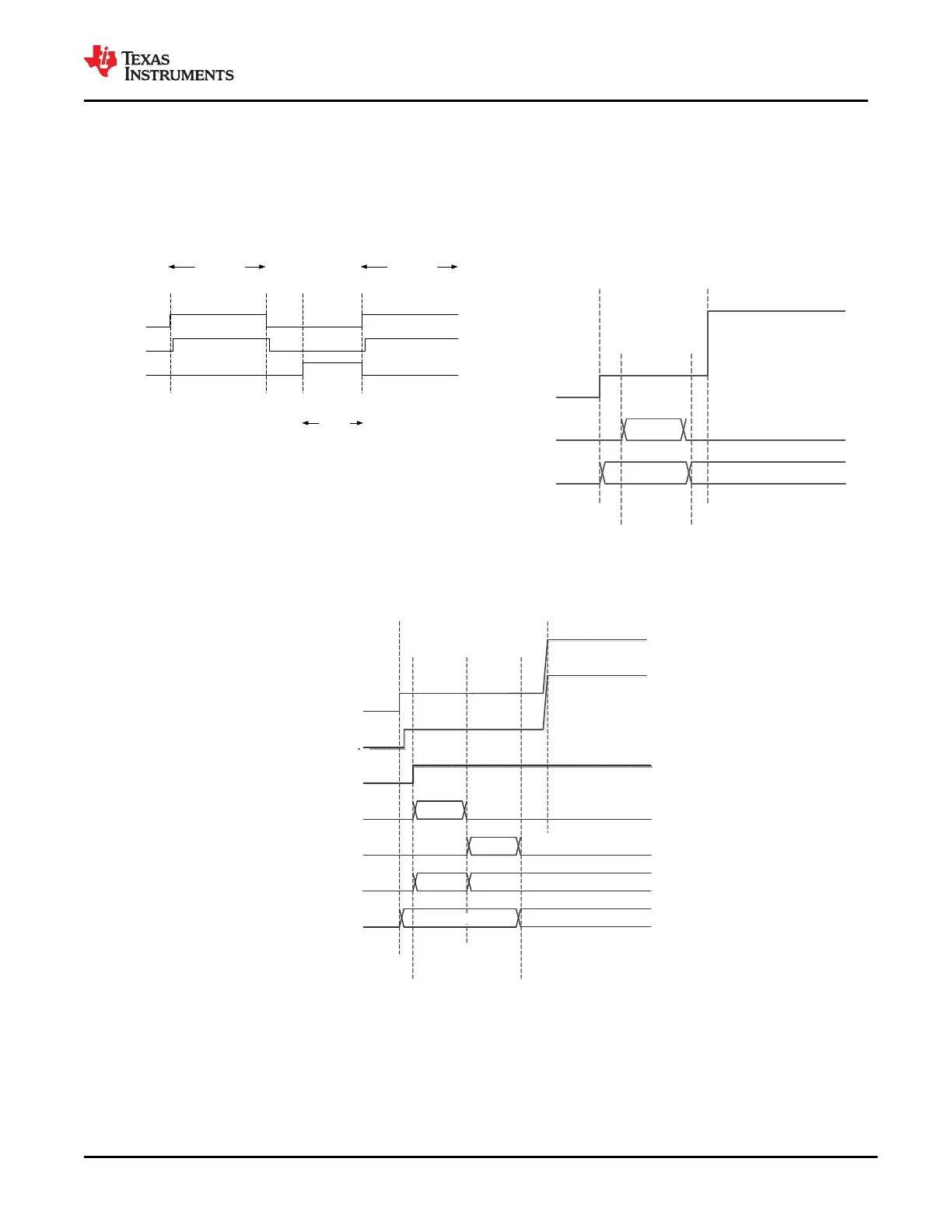
10.2.2.3 Application Curves
DC Barrel Jack
Attached
DC Barrel Jack
Detect/PFET Enable
Type-C
Charging
Barrel Jack
Inserted
Barrel Jack
Removed
Enter 20 V Type-C
PD Contract
Barrel Jack
Inserted
Exit 20 V Type-C
PD Contract
Barrel Jack Charging Barrel Jack Charging
PD Charging
Figure 10-7. DC Barrel Jack and Type-C PD
Charging Hand-Off
Type-C Cable
Connected
Flash FW
Load Start
Boot
Application
Load
PD Comm.
Enabled
20 V PD Power
Contract
VBUS
Application
FW Load
Active
TPS65982 Code
0 V
5 V
20 V
Figure 10-8. Primary TPS65982 Dead Battery
Sequence
Type-C Cable
Connected
SPI LOAD
Primary
TPS65982 Loads
App. FW (SPI)
20 V PD Power
Contract
Secondary
VBUS
Primary
Application
FW Load
Primary Active
TPS65982 Code
0 V
5 V
20 V
Secondary
PP_EXT
0 V
5 V
BQ Charger
3.3 V Auxiliary
(VIN_3V 3)
0 V
3.3 V
UART LOAD
Secondary
Application
FW Load
Secondary Active
TPS65982 Code
Secondary
TPS65982 Loads
App. FW (UART)
Secondary PD
Communication
Enabled
20 V
Boot
Application
Boot
Application
Figure 10-9. Secondary TPS65982 Dead Battery Sequence
www.ti.com
TPS65982
SLVSD02E – MARCH 2015 – REVISED AUGUST 2021
Copyright © 2021 Texas Instruments Incorporated
Submit Document Feedback
89
Product Folder Links: TPS65982