21
August ’01 Chapter 2. Electrical Description
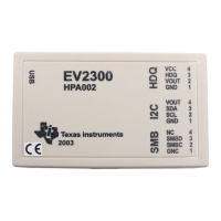
Figure 8: Test Arrangement with Digital Interface Test Box and PC
The test interface consists of two input pins (TEN, TCLK) and one input/output pin (TDAT).
The digital input/output levels are referenced to VBAT, which can also be supplied via the
test interface if the battery is removed. The input TEN has a double function: after activation
of the Test Mode the programming voltage (VPP) is supplied via this pin.
TEN = 0V: Shift data in TDAT using TCLK
TEN = VBAT: Activate Test, decode test mode and switch test signals or data to
TDAT.
TEN = VPP: Apply programming voltage for EEPROM. TEN must already be at
VBAT, before programming voltage is applied.
TCLK = 0V: Prepare data at TDAT
TCLK = VBAT: Shift TDAT condition at positive transition
TDAT = 0: Low data. Change at negative transition of TCLK.
TDAT = VBAT: High data, externally supplied. Change at negative transition of TCLK.
TDAT = X: TDAT is digital output in certain test modes.
CL
VCL
GND WAKE
VBAT
EOBA
GND
UHF TRANSMITTER
WDEEN
VCCO
VCC
RF1
RF2
RF3
TIMERINT/INP INT/INPOUT
TCLK
TDAT
OUT
LR1
CR1
TEN
3-D ANALOG FRONT-END
TMS37122
MICROCOMPUTER
OUT
MOD
LR2LR3
CR3
CR2
TX
OUT
PASSIVE ENTRY/ PASSIVE START TRANSPONDER WITH BATTERY BACKUP FUNCTION
CLKA/M
PC
15 V
POWER
SUPPLY
VAR.
POWER
SUPPLY
VAR.
POWER
SUPPLY
IEEE
LEVEL SHIFTER
3DTST01B.DRW
µC
RS232
DIGITAL
INTERFACE
TEST
BOX

 Loading...


