23
August ’01 Chapter 2. Electrical Description
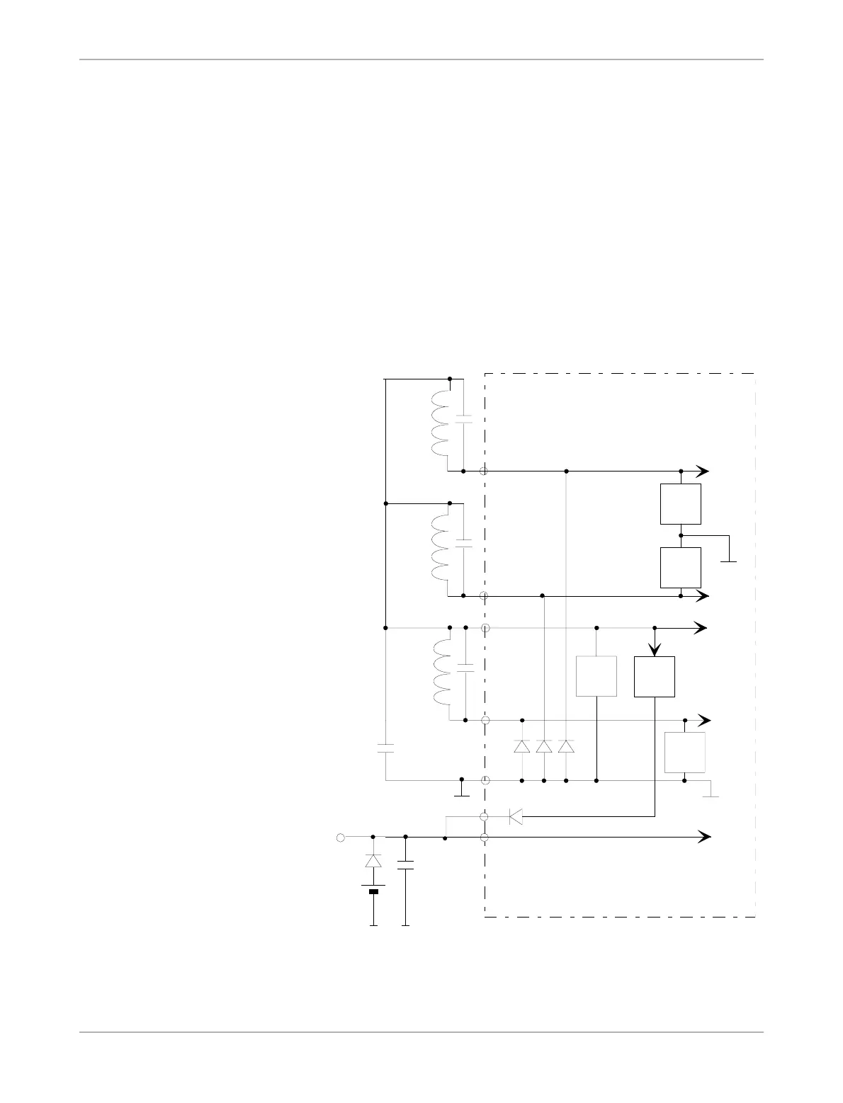
2.4 Limiter Circuits
The TMS37122 has separate Limiter Circuits at the RF inputs, which prevents the high volt-
age parts of the circuit from overload (see Figure 10). The circuit limits the positive half-wave
with respect to ground. The negative half-wave is clamped to ground by the Rectifier Diode.
The peak-to-peak amplitude is therefore approximately two times the VCL voltage.
The common VCL pin has an additional VCL Limiter circuit. In case of strong fields the RF
signal can become very unsymmetrical and therefore the VCL could increase stronger than
the RF amplitude. In this case the VCL Limiter prevents the low voltage parts from being
overstressed.
The Voltage Regular characteristic also achieves a limitation of the VCCO voltage. Under all
VCL conditions the VCCO voltage will not exceed 4 V.
Figure 10: TMS37122 Limiter Circuits
VOLT.
REG.
VBAT
3DLIM01.CH4
CR
LR
GND
VCL
RF1
µC
VCCO
RECTIFIER
DIODES
VCL
VBAT
VCL
LIMIT.
RF
LIMIT.
CR
LR
RF2
CR
LR
RF3
RF
LIMIT.
RF
LIMIT.
RF3
RF1
RF2