44
Analog Front End IC TMS37122 - Reference Guide August ’01
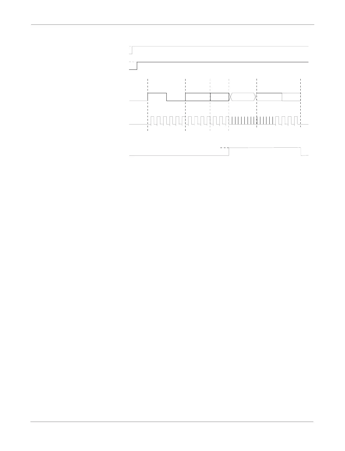
Figure 25: Timing Diagram for Test Mode PTx07
2.11 Resonant Circuit Trimming
The three Resonant Circuits (LR,CR) connected between VCL and the inputs RF1, RF2 and
RF3 need to be trimmed to the optimal system frequency (fTX) in case the tolerances of the
inductance and the external capacitor are too high. Especially for the Battery Backup and
Charge Function an accurate trimming is important because of the energy transfer to the
charge capacitor CL is better.
Each RF-input has a certain input capacitance CIN with respect to GND, which must be taken
into consideration during definition of the resonant circuit components. This capacitor de-
creases with increasing VCL (CRF1, CRF2, CRF3).
As well as this, an 8-bit capacitor array is provided at each RF-input. The Trimming Capac-
itors are activated or deactivated by means of 8-bit EEPROM cells. Per default all capacitors
are programmed off. The external components are selected in a way that the resonant circuit
frequency range resulting from the parameter variations without Trimming Capacitors (but
with Input Capacitance) is below the desired frequency. By switching (programming) on the
binary weighted capacitors the resonant circuit range can be shifted up to achieve symmetri-
cal distribution around the system frequency.
In case the LF Transmission function is used, also the non-configurable Modulation Capaci-
tor (CM) must be taken into consideration when the resonant circuit components are defined.
The resulting frequency hub is depending on the used components and must be adapted to the
Base Station Requirements.
The system manufacturer has to trim the Identification Device after assembly using the Trim/
Test Interface. The following Test Modes are provided:
- PTx14 Programming of Antenna 1 trim byte (on and off)
- PTx24 Programming of Antenna 2 trim byte (on and off)
- PTx34 Programming of Antenna 3 trim byte (on and off)
112345
LSB
VBAT
TDAT
TCLK
TEN
23
ROW NIBBLE
12
LSB LSB
VBAT
WDEEN
TEST MODE
PTx07
64319
DATA OUT
1234
undefined
3DTMOD7.DRW
1 5
BIT 1 BIT 2-4