61
August ’01 Chapter 4. Product Specification Data
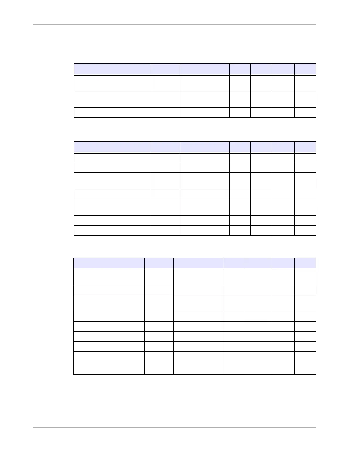
4.2.3 Recommended Operating Conditions for IC
4.2.3.1 Identification Device Antennas
4.2.3.2 Resonant Circuit Capacitor
4.2.3.3 Charge Capacitor
Parameter Sign Note Min Nom Max Unit
Inductance of antenna for
fRES=134.2kHz
LR1,LR2,
LR3
25 ºC CR1,2,3 =
470 pF +/- 5%
2.37 2.47 2.57 mH
Capacitance of LR1, LR2,
LR3
CLR 11 pF
Quality factor QLR 33
Parameter Sign Note Min Nom Max Unit
Resonant Circuit Capacitor CR fRES = 134.2kHz 446.5 470 493.5 pF
Dielectric NP0
Temperature Coefficient of CR
(NP0)
dCR/
CR*dT
+/-30 73 ppm/K
Dielectric R2H
Temperature Coefficient of CR
(R2H)
dCR/
CRdT
-220/
+60
ppm/K
Quality factor QCR 1000
Operating Voltage RF 20 50 Vpp
Parameter Sign Note Min Nom Max Unit
Charge capacitor CL
Backup Function
not used
10 22 33 nF
Dielectric of CL CLdiel X7R
Charge Capacitor
Temperature Variation
dCL(T)/
CL
+/-10 %
Charge Capacitor Aging dCL(t)/CL +0/-5 %
Insulation resistance Rins <16 dc 4 GΩ
Dissipation factor DF 0.035
Operating voltage VCL 10 16 Vdc
Charge capacitor CLbup
Backup Function
used
Itot*
tTELEGR
/3V
F