42
Analog Front End IC TMS37122 - Reference Guide August ’01
2.10.4 Memory Programming
For Programming Test Mode PTx04, TDAT, TCLK and TEN must be connected to a Tester
Unit (see Figure 8). The circuit must be supplied by VBAT and must be activated (Standby
Mode) during all test functions (WDEEN=high).
The Test Mode is addressed by shifting in the 6-bit test number (04hex) using TDAT and
TCLK input (see Figure 24). All data must be supplied with LSB first and the High state at
every input must have VBAT level. TDAT condition should be changed at the negative tran-
sition of TCLK. The data are shifted in with positive transition. After the Data to be pro-
grammed the Row and Nibble information is shifted. Row and Nibble address is binary
coded. After that 16 clocks must be supplied while TEN is high in order to clock the internal
Control Unit. Then the level at TEN can be increased to VPP level and programming is exe-
cuted. Rise and fall time of VPP must be observed.
With deactivation of TEN the circuit resets automatically and is ready for next test command.
VBAT and/or WDEEN must not be initialized.
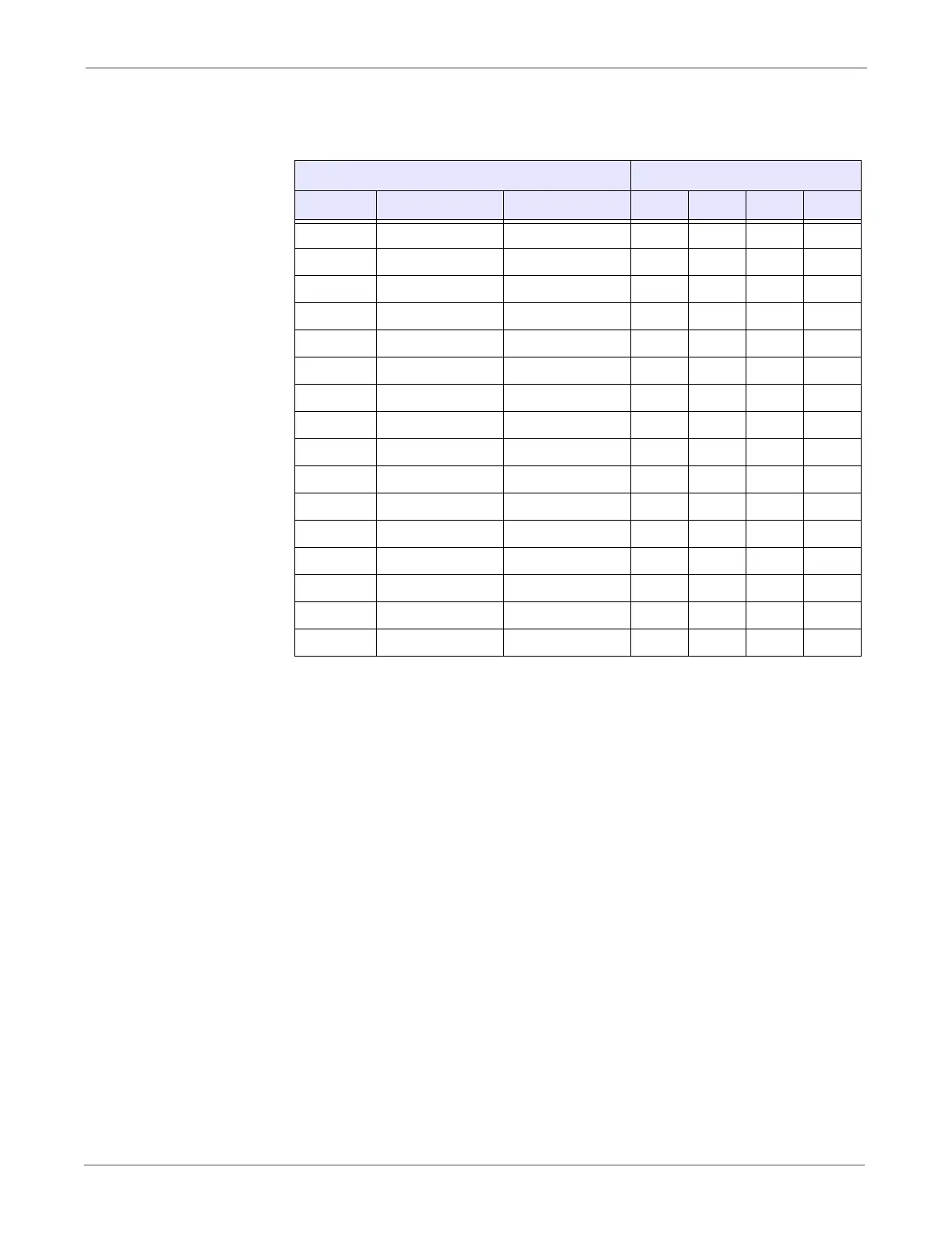
Table 7: Wake Pattern Waiting Time Options
Wake Pattern Waiting Time
DEC cwait ttwait nom.[ms] MSB LSB
0 1024 7.6 0 0 0 0
1 2048 15.3 0 0 0 1
2 3072 22.9 0 0 1 0
3 4096 30.5 0 0 1 1
4 5120 38.2 0 1 0 0
5 6144 45.8 0 1 0 1
6 7168 53.4 0 1 1 0
7 8192 61.0 0 1 1 1
8 9216 68.7 1 0 0 0
9 10240 76.3 1 0 0 1
10 11264 83.9 1 0 1 0
11 12288 91.6 1 0 1 1
12 13312 99.2 1 1 0 0
13 14336 106.8 1 1 0 1
14 15360 114.5 1 1 1 0
15 16384 122.1 1 1 1 1