29
August ’01 Chapter 2. Electrical Description
The supply current decreases because only one Wake Detector remains active (Iact).
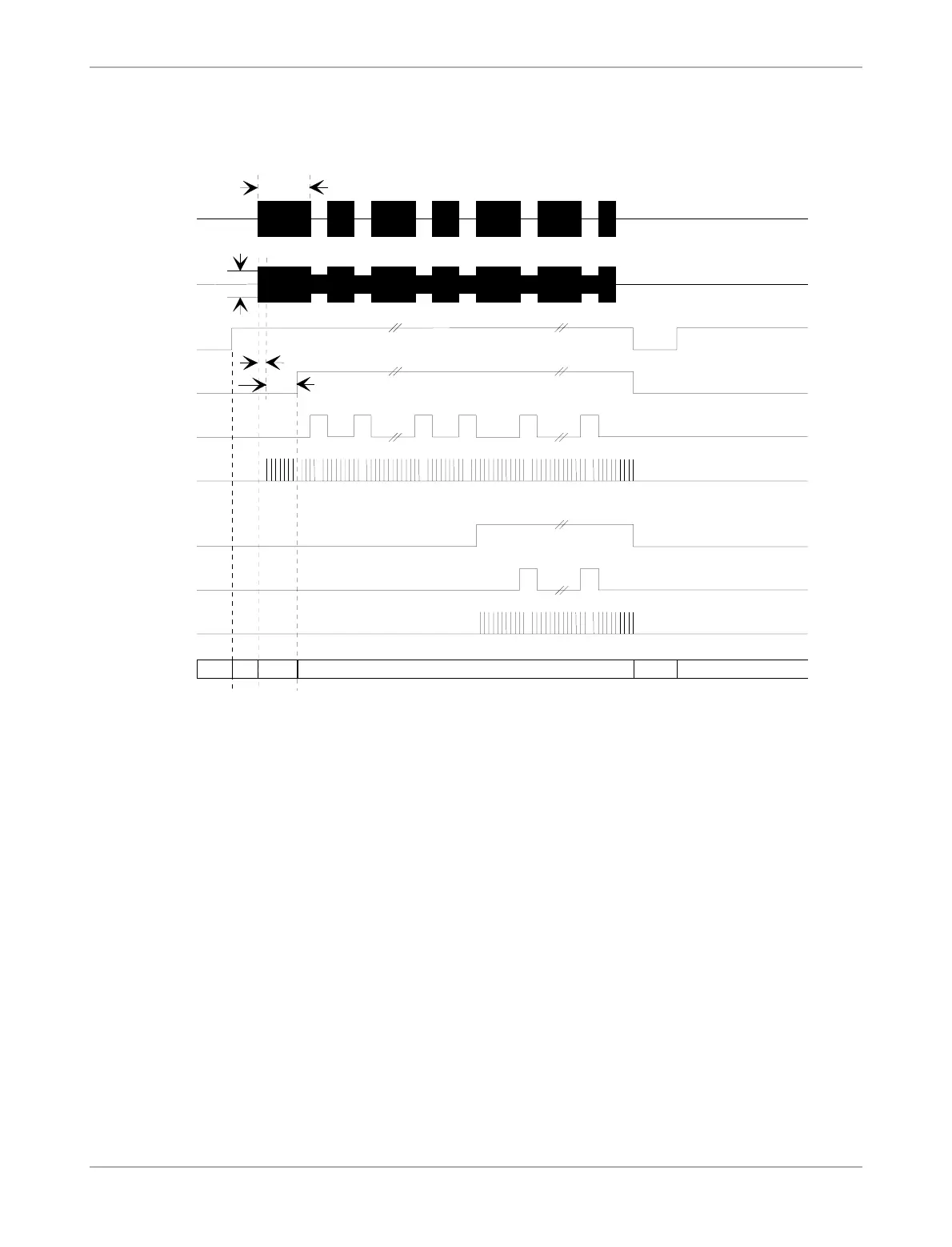
Figure 15: Control Unit Timing Diagram
2.8.4.1 Wake Pattern Detection
If the Wake Pattern Detection function is activated, the following 17 EOBI signals are inter-
preted as Pulse Position Modulation (PPM) telegram.
If no EOBI signal is detected within a via Off-Mode Memory defined time (twait), the Con-
trol Unit returns to the Standby Mode (via Off-Mode) again (see Figure 16). This is achieved
by switching off the CLKI so that the Standby Mode is entered after t = twait + twdg due to
Watchdog function. During twdg the current consumption is reduced significantly.
With the first detected EOBI signal the circuit enters the Wake Pattern receive loop. The com-
plete Wake Pattern must be received in a predetermined time (twrx) to be accepted. This time
is not configurable.
If no valid or complete Wake Pattern is detected during twrx, a waiting loop is entered. In this
loop the circuit remains for an expected time a foreign Identification Device needs to com-
plete its telegram transmission (ttelegr). Then the Standby Mode is entered via Watchdog.
Any CLKI interruption longer than twdg causes the circuit to return to Standby Mode (via
Off-Mode) and resetting the complete sequence control. Also the Configuration Memory
contents are reloaded to the relating locations.
After receipt of a complete 16-bit Pattern, the PPM Demodulator checks if the Passive Entry
WDEEN
VWAKE
RFreader
RFtrp
tPdly
tWdly
tWAKE
WAKE_I
EOBI
CLKI
EOBA
WAKE
CLKA/M
IBAT
Iquiet Istby IactIinit Iquiet Istby
3DTIM00A.CH4