ux
12V
Zones
7 & 8
Zones
1 & 2
Zones
3 & 4
Outputs
1 to 8
Speaker
Output
Aux
Input
Address
Switch
Connecting Expanders
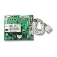
Expanders are connected to the network terminals located at
the bottom left hand corner of the control panel (see pages
12 & 13 for details).
Expander Addressing
Each Expander must be assigned a different address using
the DIL switches located in the centre of the PCB. The table
below shows the expander addressing:
Address DIL 1 DIL 2 DIL 3 DIL 4
1 On or off Off Off Off
2 431
2 Off On Off Off
2 431
3 Off Off On Off
2 431
4 Off Off Off On
2 431
5 * On Off Off On
2
* Premier 88, 168 and 640 only
Never set two expanders on the same network to the
same address.
Expander Zones
The expander has eight programmable zones (see page 19
for wiring details). Each zone is also fully programmable (see
page 35 for details).
Zone Numbering
The table below shows the zone allocation when the
expanders are installed:
Address
Zones
(Network 1)
Zones
(Network 2)
1 9 - 16 73 - 80
2 17 - 24 81 - 88
3 25 - 32 89 - 96
4 33 - 40 97 - 104
5 * 41 - 48 105 - 112
6 * 49 - 56 113 - 120
7 * 57 - 64 121 - 128
8 * 65 - 72 129 - 136
* Premier 88, 168 and 640 only
Network 2 can only be used on the Premier 168.
For Premier 640 see page 18 for details
Expander Auxiliary Input
The expander has one programmable input. This auxiliary input
can be used to monitor auxiliary devices such as tamper loops
etc. Wire as per Aux Tamper shown on page 20 (see page 59
for details). The system will respond as follows:
Input Status System Response
0V Applied Input Secure
0V Removed Input Active
EOL Various *
* For wiring details, see page 22.
For further details on how the input status affects the
system please refer to page 59.
Expander Outputs
The zone expander has eight programmable outputs, which
can be used to drive auxiliary devices such as LED’s,
sounders or relays etc. Wire as per Panel Outputs shown on
page 21 (see page 60 for details). The electrical
characteristics for the outputs are shown below:
Outputs Max Current Type
1 to 8 100mA Switched -ve
Expander Speaker Output
The expander has an output that can be used for driving up to
one 16Ω or two 8Ω loudspeakers (see page 20 for details).
Expander Lid Tamper
The lid tamper of each expander can be disabled if required
by fitting a jumper link across the centre and right hand pins
of the ‘Enable Tamper’ pins (JP2) leaving the left hand pin
free. These pins are located to the left of the address DIL
switch just beneath the fuse.

 Loading...

