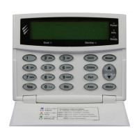
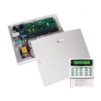
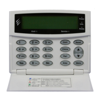
Installation Premier 48, 88, 168 & 640 Installation Manual
20 INS176
Double Pole
Use this wiring configuration when connecting normally
closed or normally open detection devices to the zone using
4-Wires.
When using Double Pole wiring, the system will respond as
follows:
Zone Status System Response
‘A’ Closed Zone Secure
‘A’ Open Zone Active
‘T’ Closed Tamper Secure
‘T’ Open Tamper Active
Short Circuit * Zone Active or Tamper
* Can be programmed for ‘Active’ or ‘Tamper’
response (see page 50 for details).
When using this configuration, no more than 10
detectors can be connected to each zone.
When wiring device as normally open contacts, ensure that
system Config. option 21 is set to ‘Zone Short = Active’ (see
page 50 for details).
Auxiliary Tamper Connections
The Auxiliary Tamper terminals allow the control panel to
monitor the tamper loops of external devices such as power
supplies etc.
If the ‘Auxiliary Tamper’ terminals are not being used
they must be linked out.
Speaker Connections
This output can be used for driving up to one 16Ω or two 8Ω
loudspeakers as shown below:
For details on testing Speaker outputs, see page 92.
External Sounder Connections
The following terminals have been provided for connection to
an external sounder:
(A)
+
12V
12V supply (protected by a 1A fuse F4). Normally connected
to ‘+12V’ on the sounder.
(B) Bell –
Sounder output, switches to 0V in alarm (SAB) and is rated at
500mA. Normally connected to Trigger -ve on
the sounder. This output can also be programmed for SCB
operation (see page 48 for details).
(C) Tamp
Negative tamper return. Normally connected to ‘Tamper Out’
on the sounder. If this terminal is not being used, it ust be
connected to ‘0V’.
(D) 0V
0V supply. Normally connected to ‘0V’ on the sounder.
(S) Strb –
Strobe output, switches to 0V in alarm and is rated at 500mA.
Normally connected to strobe -ve on the sounder (where
applicable, connect the strobe +ve to +12V).
Te x e c o m E xt e r n a l
Sounder
Control
Panel
+12V (A)
0V (D)
Tam p e r ( C )
Strobe -ve (S)
Trigger -ve (B)
For details on testing the ‘Bell’ outputs, see page 92

 Loading...

