INS303-5 8/22
Installation
Remove all power from control panel before making any connections.
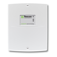
Install the module in the required location making sure that it is mounted1.
away from metal objects and other cables as these can affect the
performance of the unit.
Connect the network connections of the module to the network connections2.
of the control panel.
Connect the optional devices such the door strike, RTE button and3.
loudspeaker.
Set the Internal/External coil jumper links 14 to Internal (Int).4.
Ensure that Options switch 1 is set to ON (Internal Prox. Enabled) and5.
switches 2, 3 and 4 are set as required, (see chapter 3.1)
Using Address switches set the address of the module to one of the6.
available keypad address slots, (see chapter 3.1).
Re-apply power to the control panel and select the engineer’s programming7.
mode.
Select the “Confirm Devices” option within the “Engineer Utils” menu and8.
confirm that the module is being “seen” as a remote keypad on the system.
If the relay on the iProx is utilized, it is controlled by the relevant remote9.
keypad output. Select the “Keypad Outputs” option within the “System
Outputs” menu and program it to the required type, e.g. “Door Strike”.
If required learn any new tags then exit the engineer’s mode.10.
Check that the iProx and proximity tags operate correctly.11.
 Loading...
