Premier Elite Ricochet Kits Quick Guide
22 INS626
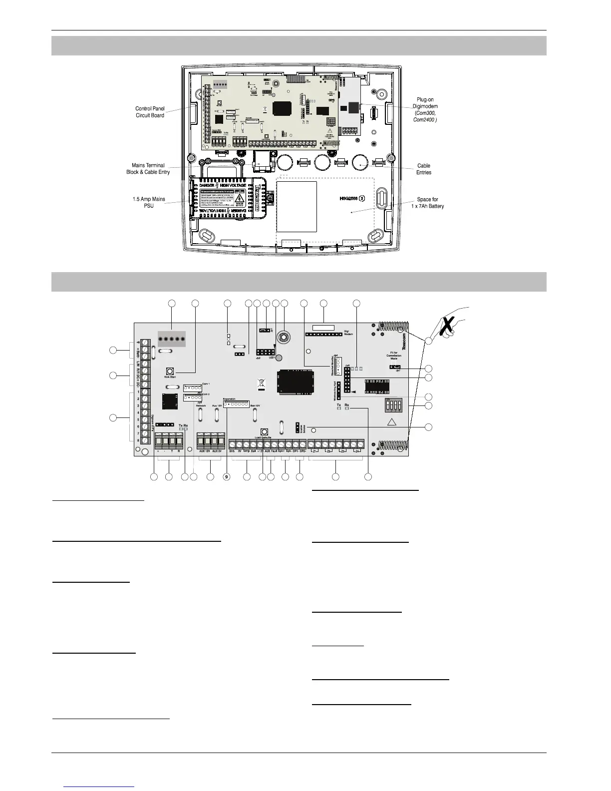
Control Panel Layout (
Premier Elite™
48-W Shown)
PCB Layout (48-W Shown)
1: Battery Connections
A 12V rechargeable battery must be connected to these terminals in
order to provide continuous system operation in the event of an AC
Mains failure. (protected by 1.6 Amp PTC Fuse)
2: Digicom Power & Inputs (24/48-W Only)
These terminals provide un-fused power; remote reset and line fault
inputs and are normally used for connecting a stand-alone
communicator to the control panel.
3: Digicom Outputs
Outputs 1 to 8 are low current (100mA ‘-ve’ applied) and would
normally be used when connecting a stand-alone communicator to
the control panel. Each output is fully programmable.
Outputs 4-8 are not fitted on the 12-W
4: Engineers Keypad
A portable Engineers keypad can be plugged on here to allow easier
access for programming and testing.
When using a keypad as an Engineers keypad, the address must
be set to ‘10’. The keypad zones and lid tamper are not monitored.
5: Network Data Connections
Network 1 provides connection for the keypads and zone expanders.
The ‘+’ and ‘–’ terminals provide power whilst the ‘T’ transmits data
and ‘R’ receives data.
6: Network Data Indicators
The red LED indicates that data is flowing out of the control panel
and normally flashes very quickly. The green LED indicates that data
is flowing into the control panel and normally flashes slowly, the
green LED flashes faster as more devices are connected.
7: Communication Ports
Com Port 1 is a serial communications port and can be used for
connecting a PC running Wintex or any supported serial device to the
control panel.
Com Port 2 is a serial communications port and can be used for
connecting a PC running Wintex or any supported serial device to the
control panel.
8: Auxiliary 12V Power
These terminals are for connecting devices that require 12V power
(protected by a 0.9A PTC fuse).
9: Expansion
The Expansion Port can be used for connecting a 60XiD Zone
Expander or an AV Module.
10: External Sounder Connections
These terminals are used for connecting to an external sounder unit.
11: Load Defaults Button
Press and hold this button whilst applying power to the control panel
to load the factory default settings. Press and hold this button for 7
seconds with power already on the panel to restore just the Engineer
code to the factory setting of
.
 Loading...