Premier Elite Ricochet Kits Quick Guide
INS626 7
Connecting Keypads & Expanders
Before connecting keypads, zone expanders and output modules, isolate ALL power from the control panel (AC Mains & Battery).
Do not continue if there is still power present on the control panel.
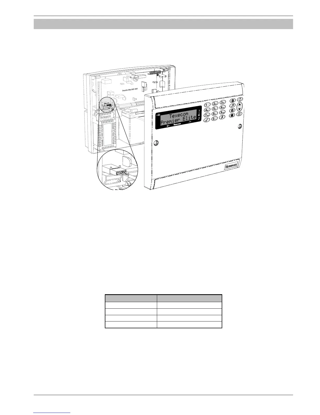
Premier Elite 12/24 & 48-W Live Front
Panels with an integral keypad are already wired and should be connected as shown.
Connecting devices with power still present on the control panel may damage the device or control panel and invalidate any
warranty.
Keypads, zone expanders and output modules are all connected to the same network terminals located at the bottom left hand corner of
the control panel and may be connected serially (daisy chain), in parallel (star) or any combination of the two (see Figure 1, page Error!
Bookmark not defined. for details).
No more than 8 zone expanders, 8 keypads and 4 output modules can be connected to each network.
The maximum number of devices that can be connected in total will depend on the control panel fitted.
Whenever new devices are connected to the networks, they must be confirmed onto the system using the ‘Confirm Devices’ menu
option
Wiring the Network
The networks are made up of four terminals incorporating power and data. To ensure correct operation, all four terminals on the
device must be connected to the corresponding terminals on the control panel, or previous device (see Figure 1, page Error!
Bookmark not defined. for details). The table below shows each terminal and its description:
Terminal Description
+ +12V Supply
- 0V Supply
T Transmit Data
R Receive Data
Devices can be connected using 4-core cable. However, it is recommended that 6 or 8-core cable is used as the spare cores can be used to
‘Double Up’ on the power connections if needed.
Standard 7/0.2 alarm cable can be used for most installations. However, under certain conditions it may be necessary to use
screened cable. Cable used should be rated at no more than 10Ω per 100mtr's and should be clearly marked on the
packaging.
 Loading...