©Copyright Task Force Tips, Inc. 2004-2018 LIX-530 December 31, 2018 Rev14
10
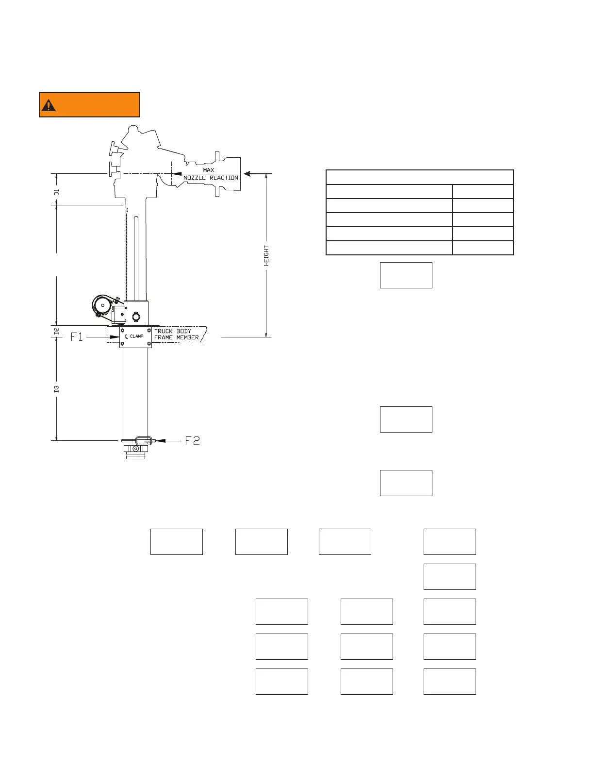
7) Multiply L x R L x R = M inch • pounds
8) Divide M by D3 M / D3 = F1 pounds
9) Subtract R from F1 F1 - R = F2 pounds
5.0 SIDE LOADS AT MOUNTING POINTS
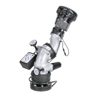
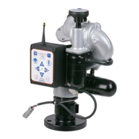
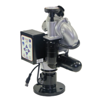
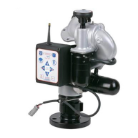
5.1 12” EXTEND-A-GUN RC3
12” extend-a-gun rc3
WARNING
Before installing the Extend-A-Gun RC you MUST determine the forces that will
be exerted in the proposed installation by the reaction force of the nozzle.
1
R
15.7”
1) Determine the distance, D1, in inches, from the center of
the monitor elevation joint to the bottom of the threads in the
monitor inlet.
D1 FOR MOST COMMON INSTALLATIONS
Task Force Tips CROSSFIRE D1 = 2"
Task Force Tips HURRICANE D1 = 6"
Task Force Tips MONSOON D1 = 13"
Task Force Tips TORNADO D1 = 13"
Task Force Tips TYPHOON D1 = 19”
D1 = inches
2) Locate the value of D1, in the charts on page 11. Find the
desired HEIGHT from the center of the upper bracket to the
center of the stream.
3) Locate D2, the distance from the bottom of the latch
casting to the center of the upper mounting bracket, for the
chosen HEIGHT. (inches)
D2 = inches
4) Determine the distance, D3 in inches, from the center of the upper
mounting bracket to the center of the lower mounting bracket for the
proposed installation. D3 MUST be between D3 min and D3 max.
D3 = inches
5) Calculate forces on Brackets, Add D1 + D2 + D3 + 15.7 =
D1 + D2 + D3 + 15.7 = L inches
6) Determine R maximum nozzle reaction from load charts on page 11. R = pounds
 Loading...