©Copyright Task Force Tips, Inc. 2004-2018 LIX-530 December 31, 2018 Rev14
19
3) Unscrew monitor until a pair of 90 degree apart slots lines up with the 180 degree apart threaded cross-holes in the Extend-A-
Gun RC.
A) Orient monitor so that the “Straight Ahead Reference Mark” is facing the desired direction.
B) Slots will line up with threaded cross-holes every 90 degrees of rotation.
C) Monitor may be unscrewed up to one full turn from the bottomed out position.
4) Install ¼-28 by ½ long Button Head Cap Screws and Washers in the two threaded cross- holes. Use Loctite #271 on the threads
of the Button Head Cap Screws. Allow Loctite to fully cure before applying water pressure.
TWO PIECE CLAMP ROTATIONAL LOCK INSTALLATION INSTRUCTIONS (without tapped holes):
1) Assemble Clamps and place loosely on Extend-A-Gun.
A) Apply VSA-104 blue Loctite to threads on Cylinder Nut.
B) Loosely install Screws, Washers and Cylinder Nuts on Clamp.
C) Grooves on heads of Cylinder Nuts indicate alignment of threaded holes.
D) Place Clamp assembly over male threads of Extend-A-Gun outlet.
E) Heads of Cylinder Nuts must be on top side of Clamps.
2) Screw monitor onto Extend-A-Gun RC until threaded joint bottoms out.
A) CAUTION: Make sure the Clamps are not tight enough to prevent the monitor Base from bottoming out. The monitor will leak
if it does not bottom out in this step.
B) DO NOT USE PIPE DOPE OR LOCTITE ON THE INLET BASE THREADS. These threads are sealed with an O-ring. The
use of thread locking compounds will make removal diffi cult.
3) Unscrew monitor until the “Straight Ahead Reference Mark” is facing the desired direction.
A) Monitor may be unscrewed up to one full turn from the bottomed out position.
B) CAUTION: Monitor will leak if unthreaded more than one full rotation from bottomed-out condition.
4) Rotate the Clamps to the desired orientation.
A) Ensure that Clamp assembly does not interfere with RC monitor Power/Com Cable.
5) Tighten each Screw gradually until both are fi nger tight with approximately equal spacing between opposite ends of Clamps.
6) Carefully tighten each Screw one additional turn using a 5/32 hex wrench by alternating to the opposite Screw in half turn
increments.
A) CAUTION: Over tightening the Screws will damage Screws and Clamps.
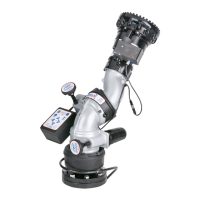
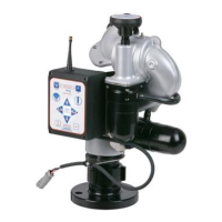
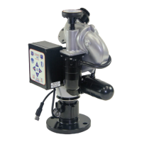
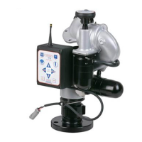
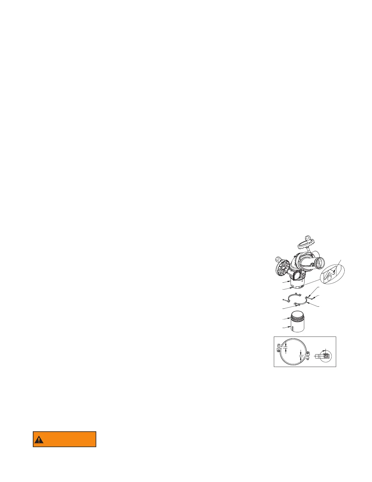
10.2 CROSSFIRE ON EXTEND-A-GUN RC3
TWO PIECE CLAMP ROTATIONAL LOCK INSTALLATION INSTRUCTIONS
(without tapped holes):
1) Assemble Clamps and place loosely on Extend-A-Gun.
A) Apply VSA-104 blue Loctite to threads on Cylinder Nut.
B) Loosely install Screws, Washers and Cylinder Nuts on Clamp.
C) Grooves on heads of Cylinder Nuts indicate alignment of threaded holes.
D) Place Clamp assembly over male threads of Extend-A-Gun outlet.
E) Heads of Cylinder Nuts must be on top side of Clamps.
2) Screw monitor onto Extend-A-Gun RC until threaded joint bottoms out.
A) CAUTION: Make sure the Clamps are not tight enough to prevent the monitor Base
from bottoming out. The monitor will leak if it does not bottom out in this step.
B) DO NOT USE PIPE DOPE OR LOCTITE ON THE INLET BASE THREADS.
These threads are sealed with an O-ring. The use of thread locking compounds will
make removal diffi cult.
3) Unscrew monitor until the “Straight Ahead Reference Mark” is facing the desired direction.
A) Monitor may be unscrewed up to one full turn from the bottomed out position.
B) CAUTION: Monitor will leak if unthreaded more than one full rotation from bottomed-out condition.
4) Rotate the Clamps to the desired orientation.
A) Ensure that Clamp assembly does not interfere with RC monitor Power/Com Cable.
5) Tighten each Screw gradually until both are fi nger tight with approximately equal spacing between opposite ends of Clamps.
6) Carefully tighten each Screw one additional turn using a 5/32 hex wrench by alternating to the opposite Screw in half turn
increments.
A) CAUTION: Over tightening the Screws will damage Screws and Clamps.
WARNING
Injury can occur from an inadequately supported monitor. The mounting must be capable of
supporting the nozzle reaction force which can be as high as 1500 lbs.
STRAIGHT AHEAD
REFERENCE MARK
10-32 X 1 1/4 LONG
SOCKET HEAD SCREW
VT10-32SH1.2
(2) PLACES
WASHER
VW360X200-04
(2) PLACES
MONITOR BASE CLAMP
(2) PLACES
MONITOR INLET
CHAMFER MATES
WITH TOP OF CLAMP
WIRE SKIRT
NOT SHOWN
FOR ILLUSTRATION
PURPOSES
INLET FITTING MOUNTED
TO EXTEND-A-GUN
OTHERS ARE SIMILAR
CHAMFER MATES
WITH BOTTOM OF CLAMP
CYLINDER NUT
(2) PLACES
EQUAL
SPACING
1 TURN PAST
FINGER TIGHT
Y4437
 Loading...