©Copyright Task Force Tips, Inc. 2004-2018 LIX-530 December 31, 2018 Rev14
18
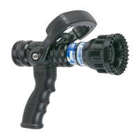
8.0 RETRACTED & EXTENDED RELAY WIRING
The RC Extend-A-Gun contains a magnetic switch that is
connected to a DOWN relay inside the control box. The magnetic
switch and DOWN relay are energized when the RC Extend-A-
Gun is in the retracted position. The control box also contains a
USER relay which can be confi gured for the installers needs (see
section 7.4). For example, to electrically lock out a water valve
so water cannot be turned on until the RC Extend-A-Gun is fully
extended. When confi gured for RC Extend-A-Gun “Extended”,
the USER relay will be energized when the RC Extend-A-Gun is
in the extended position.
5
4
1
2
3
6
View From Wire Side
DT06-6S-P012 Relay Connections
Pin
Function
1
DOWN relay common connection
2
DOWN relay normally open
3
DOWN relay normally closed
4
USER relay normally closed
5
USER relay normally open
6
USER relay common connection
Fig. 8.0
The RC Extend-A-Gun control box includes a cable that is pre-connected to the internal relays for easier access and to prevent
the waterproof seal from being damaged from improper re-installation of the lid. The 6-conducter wire and receptacle includes a
Deutsch DT06-6S-P012 6-position plug for easy connection. There are easily removed sealing plugs inserted into each wire position
to prevent water from entering the connector when there is no wire inserted into the connector position. Use size 16 contacts for all
positions. Maximum allowed current draw through relay contacts is 10 amps. The connector pin confi guration is shown in Figure 8.0
viewed from the wire side of the 6-position plug.
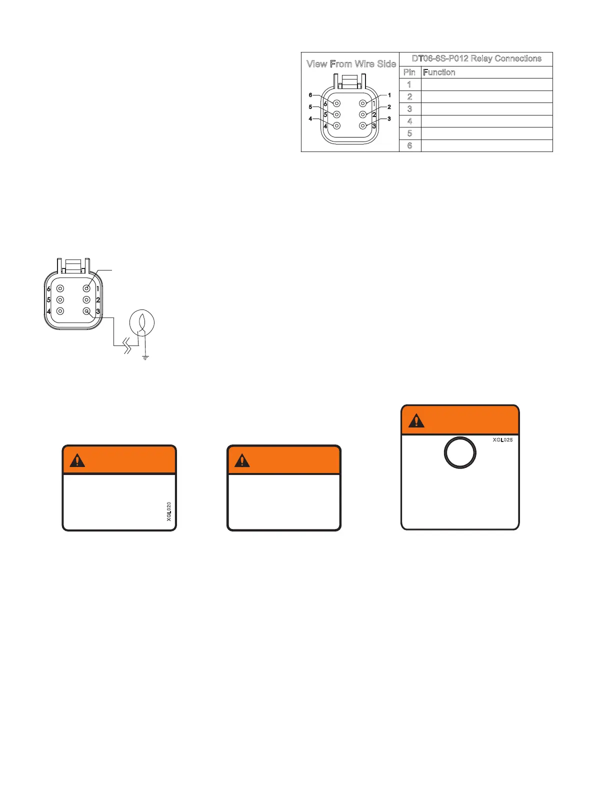
8.1 INDICATOR LIGHT MOUNTING & WIRING
MOUNT PANEL
LIGHT IN DASH
RED(+) FROM
PROTECTED
POWER
DISTRIBUTION
CIRCUIT
Fig 8.1
Many installations will use the DOWN relay for the MONITOR EXTENDED warning light or the
DOOR OPEN circuit. To install the warning light perform the following:
1) Drill a 1/2” diameter hole in the dashboard for the panel light. Leave enough room for a 1-13/16”
diameter label around the light or a 2” wide x 1-1/2” high label next to the light.
2) Apply one of the two warning labels and push the panel light through the hole in the dash.
3) Remove the seal plugs from the DOWN NC and DOWN common positions on the 6-position plug
connected to the USER/DOWN Relay cable.
4) Connect the terminals on the panel light to DOWN NC position on the 6-pin plug and chassis
ground, see fi gure 8.1.
5) Connect a wire from the DOWN common position on the 6-pin plug to positive voltage supply.
9.0 LABELS
Attach the warning label (XGL020) next to the indicator light or warning label
(XGL025) around the indicator light on the truck dashboard. Attach warning label
(XGL040) near water valve for deck monitor.
XGL025
WARNING
When Light is ON,
Deck Monitor is
EXTENDED.
Lower Before
Moving Vehicle.
When Light is ON,
Deck Monitor is
Lower Before
Moving Vehicle.
EXTENDED.
XGL020
WARNING
Do Not Open Water Valve
Until Extend-A-Gun is Fully
EXTENDED.
Damage Will Occur.
XGL040
WARNING
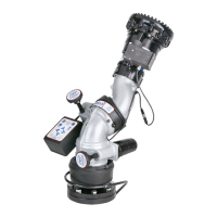
10.0 MOUNTING MONITOR
10.1 TORNADO, HURRICANE, TYPHOON AND MONSOON
Task Force Tips Tornado, Hurricane, Typhoon and Monsoon® monitor(s) may be mounted directly on the Extend-A-Gun RC. The
monitors are attached to the Extend-A-Gun RC by means of a threaded joint with an O-ring seal. Two diff erent methods of rotational
locking between the monitor Base and the Extend-A-Gun Inner Tube exist. One method relies on two ¼-28 Button Head Cap Screws,
and the other, newer version, uses a two-piece Clamp that is held together with #10 Cap Screws and Cylindrical nuts. The rotational
locking method employed can be identifi ed by the presence or absence of two threaded cross-holes, 180 degrees apart in the
threaded portion of the Extend-A-Gun Inner Tube, where the monitor Screws onto the Extend-A-Gun. If ¼-28 Screws are needed,
there will be ¼-28 threaded cross-holes in the threaded portion of the Extend-A-Gun Inner Tube. If Clamps are needed, there will be
no ¼-28 threaded cross-holes in the threaded portion of the Extend-A-Gun Inner Tube. Once the necessary rotational locking method
is determined, install the monitor using one of the following procedures.
¼-28 BUTTON HEAD CAP SCREW ROTATIONAL LOCK INSTALLATION INSTRUCTIONS (tapped holes):
1) Mount so that 180 degree apart threaded cross-holes will give desired direction relative to the “Straight Ahead Reference Mark”
when the monitor is installed. See appropriate section in your monitor installation manual.
2) Screw monitor onto Extend-A-Gun RC until threaded joint bottoms out.
A) Do not use pipe dope or Loctite on the Inlet Base threads. These threads are sealed with an O-ring. The use of thread locking
compounds will make removal diffi cult.
 Loading...