©Copyright Task Force Tips, Inc. 2004-2018 LIX-530 December 31, 2018 Rev14
15
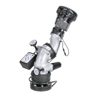
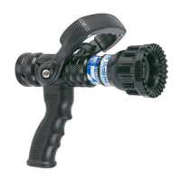
6.0 MANUAL OVERRIDE
Each Extend-A-Gun RC is equipped with an override knob. In the event of power loss, turn the knob clockwise to raise the tube or
counterclockwise to lower it.
6.1 REMOVING MANUAL OVERRIDE KNOB
The manual override knob may be removed if desired. A hex is
provided for wrenches with 1/2” (13mm) wrench or socket.
HEX FOR 1/2"
OR 13MM WRENCH
L
O
W
E
R
R
A
I
S
E
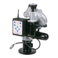
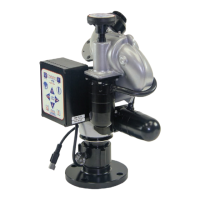
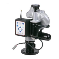
7.0 CONTROL BOX INSTALLATION
The Extend-A-Gun RC assembly contains a control box, which houses the electronics that control the electric motor, and an optional
panel mount operator station. The panel mount operator station installation is optional and not required if using RC monitor operator
stations for control. Most of the wiring has been factory installed so the installation of this control box will include mounting the control
box and connecting the wires. A 14-gauge power & communications cable, 10 ft (3m) long, is supplied for connection to the power
source and RC monitor communication link. A 14-gauge cable, 12 ft (3m) long, is provided for connection to the RC Extend-A-Gun
motor. A 14-gauge cable, 12 ft (3.6m) long, is provided for connection to the RC monitor mounted on top of the RC Extend-A-Gun. If
longer length is needed, consult factory. The RC Extend-A-Gun is designed to operate on 12V DC or 24VDC. The RC Extend-A-Gun
control box and motor are not rated as ignition proof, explosion proof, or intrinsically safe.
WARNING
The electric motor and other components are ignition sources. The electric Extend-A-Gun RC
should be operated only in areas where there is adequate ventilation and no hazard of fl ammable
vapor buildup.
CAUTION
An inadequate power supply will not drive the electric motor causing a failure to extend the
telescoping waterway which will limit the operating range of the monitor. This will result in an
increased risk of injury because the eff ectiveness of the monitor is reduced. Avoid use of thin
conductors or long cable. Check installation to insure that a minimum voltage of 10 VDC is
present when motor is running.
CAUTION
The control box provides electrical braking to keep the Extend-A-Gun from lowering too quickly.
Do not operate the Extend-A-Gun RC disconnected from the control box to avoid damage and
possible injury. The electronic braking is active even with no electrical power supplied.
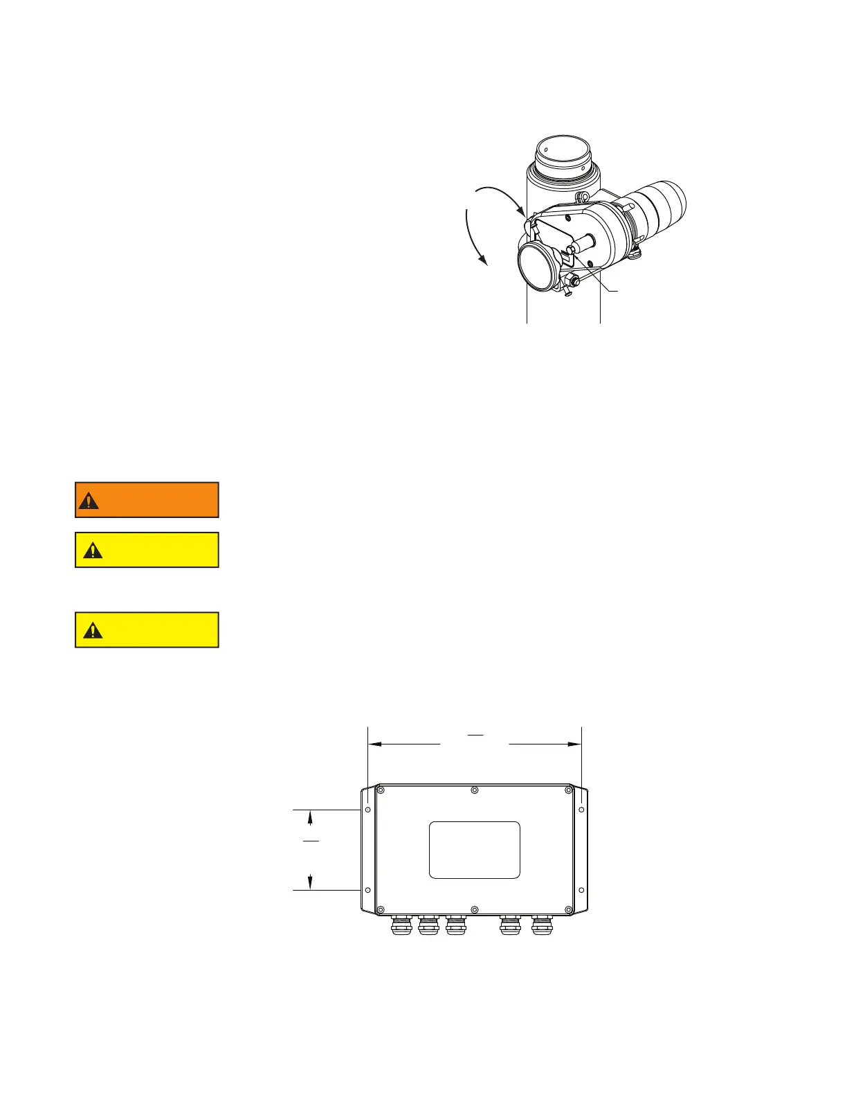
7.1 CONTROL BOX MOUNTING
Select proper operator location. Enclosure is designed to be surface mounted and the size is 5 3/4” x 8 3/4” (146 x 222mm). Height
of the enclosure is 2 1/4” (57mm) 5 3/4” x 10” (146mm x 254mm). Refer to Figure 7.1 for mounting hole dimensions.
3
9
16
"
[90mm]
9
7
16
"
[239mm]
Fig 7.1
Electrical Enclosure Mounting Hole Dimensions
 Loading...