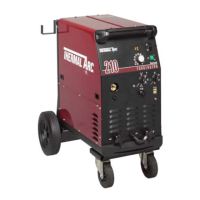
FABRICATOR 210
June 19, 2006
7-5
7.06 Output Voltage Test
A. Set COARSE VOLTAGE SELECTOR SWITCH to position "1"
B. Set FINE VOLTAGE SELECTOR SWITCH to position "1"
C. Connect voltmeter probes to + & - WELDING TERMINALS
D. Depress Gun Switch and observe voltage
E. Repeat voltage measurements in each of the 16 combinations of the OUTPUT VOLTAGE CONTROL SWITCHES.
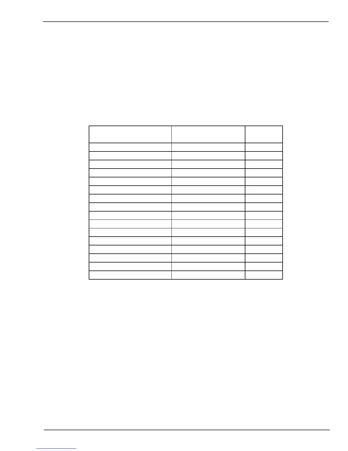
The voltages should measure approx as outlined below.
EACH SUCCESSIVE READING MUST BE INCREASING IN VALUE
COARSE VOLTAGE SELECTOR
SWITCH SETTING
FINE VOLTAGE SELECTOR
SWITCH SETTING
VOLTAGE
1 1 17.3
1 2 18.1
1 3 18.9
1 4 19.7
2 1 20.6
2 2 21.7
2 3 22.8
2 4 24.2
3 1 25.5
3227
3 3 28.8
3 4 30.8
4 1 32.9
4 2 35.3
4 3 38.7
4 4 42.1
This completes the Output Voltage Tests. If the above are all correct then proceed to paragraph 'D'. If the above does
not function as noted then note the symptom and proceed to Section 7.11 Output Voltage Test.



 To Next Page