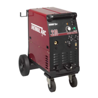
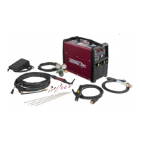
FABRICATOR 210
8-2
June 19, 2006
CONNECTOR JB
Terminal JB-1
wiper of wire speed control potentiometer,
varies between <2V to approximately 4.7VDC
(pot wiper)
reference JA-5 or JB-5
Terminal JB-2
wire speed control potentiometer minimum
(pot low) approximately 2VDC
reference JA-5
Terminal JB-3
wire speed control potentiometer maximum
approximately 4.7VDC
reference JA-5
Terminal JB-4
32VAC supply from auxiliary winding on fan
reference JA-5 or JB-5
Terminal JB-5
PCB common. Return for 32VAC supply from
auxiliary winding on M1
Terminal JB-6
Motor positive terminal 0VDC - 24VDC with
speed pot
reference JB-8
Terminal JB-7
negative welding output voltage
reference JB-9
Terminal JB-8
Motor negative terminal 0VDC to -24VDC with
speed pot
refe
rence JB-6
Terminal JB-9
positive welding voltage
Terminal JB-10
return for 32VAC supply from auxiliary winding
on M1
reference JB-5
Terminal JB-11
relay contact to control SOL1 & W1
closes to complete circuit to JB-10
reference JB-4
CONNECTOR JB
Torch circuit jumper installed
8.02 Circuit Operation Of The MIG Timer
PCB 7977965
This board is connected by way of a 6-way cable and
does not have any terminals available to measure.
8.03 Circuit Operation Of The Digital
Volt/Amp PCB 704883
Terminal X13/1
24VAC supply for board
measure 24VAC wrt X13/3
Terminal X13/2
no connection
Terminal X13/3
24VAC supply for the board
measure 24VAC
wrt X13/1
Terminal X13/4
PCB common, weld volts negative
shunt negative PCB 0V
Terminal X13/5
shunt positive
measure a few hundred mV
wrt X13/4 when welding output is loaded
Terminal X13/6
weld volts positive
measure welding output voltage
wrt X13/4