FABRICATOR 210
June 19, 2006
7-13
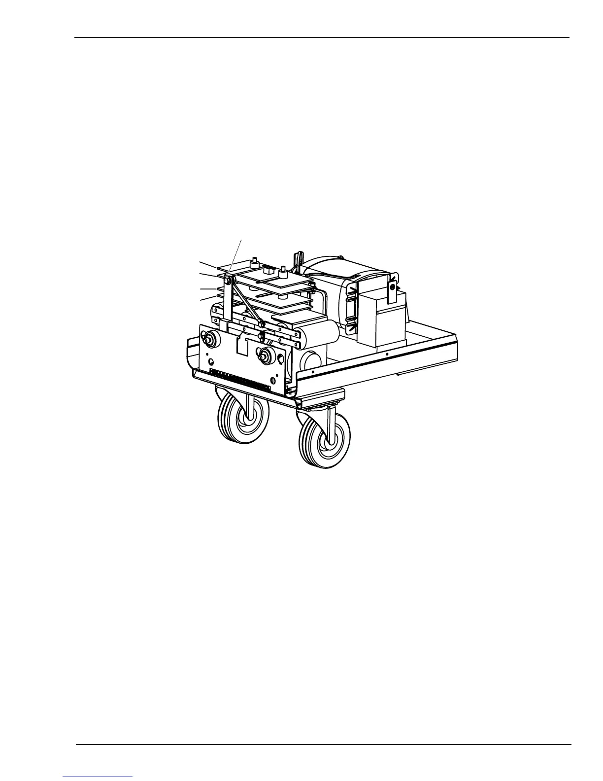
7.16 Rectifier Assembly Test
1. Disconnect one of the Main Transformer connections from the rectifier assembly.
2. Disconnect and isolate wires from the Negative output of the Rectifier Assembly See Figure 7-3.
3. Disconnect JB connector from MAIN PCB 1.
4. Using a meter check the diode readings between the following points:
Forward biased diode junction:
Positive meter probe on rectifier plates 2 and 3 to plates 1 & 4
Negative meter probe on rectifier plates 1 & 4 to plates 2 & 3
Art # A-07575
1
2
3
4
Remove and isolate from rectifier assembly
Figure 7-3: Rectifier Assembly Test
Double forward biased junction:
Positive meter probe on rectifier plates 1 & 4 to positive rectifier output terminal (Picture needed)



 To Next Page