Manual 0-2868 4-1 OPERATION
SECTION 4:
OPERATION
4.01 Introduction
This section describes the power supply operating con-
trols and procedures, identifies the front and rear com-
ponents, and describes the operating procedures.
4.02 Product Features
This subsection describes the power supply operating
controls and indicators.
A. Front and Side Panel Features
1. Control Panel
All operator controls, except gas pressure adjustment,
are on this panel.
A-02992
1
2
3
4
Front Features
2. Torch Leads Input
Hole in the front panel to feed the torch leads through
to the internal bulkhead connections.
3. Work Cable and Clamp
20 ft (6.1 m) work cable with clamp, factory installed.
4. Roll Handle/Torch Leads Wrap
The torch leads and work cable wrap around the
handle for easy storage.
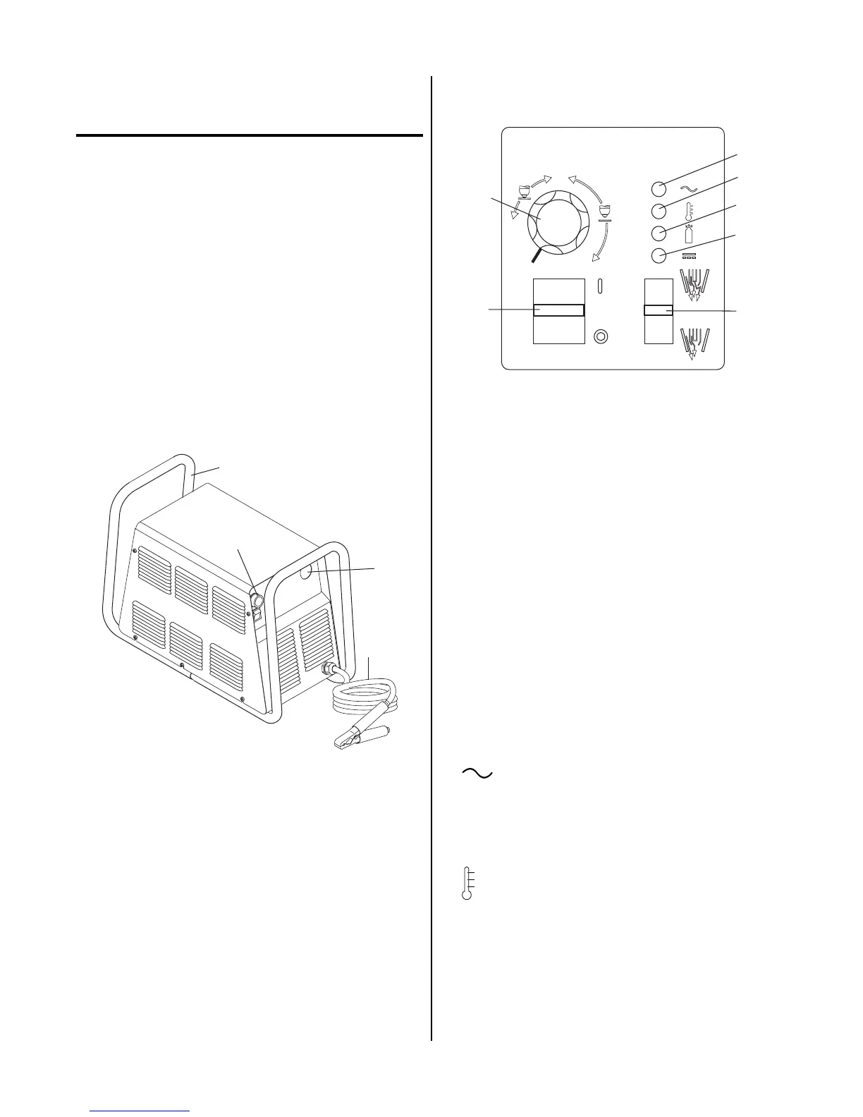
B. Control Panel Features
A-03208
A
1
4
5
6
7
2
3
20
40
60
Operating Controls
1. ON / OFF Power Switch
ON (up) position supplies AC power to activate all
system circuits. OFF (down) position deactivates con-
trol circuits.
2. RUN / SET Switch
RUN (up) position is for general torch operation.
Torch switch must be held. SET (down) position is
for setting gas pressure and purging lines.
3. Current Control (A)
Adjustment to set the desired output current up to 40
amps (for drag cutting) or up to 60 amps (for standoff
cutting). Minimum output is approximately 15 amps.
At output settings over 40 amps, control circuitry in
the power supply automatically reduces output cur-
rent to 40 amps if the torch tip contacts the workpiece.
4. AC Power Indicator
Green LED indicator will blink ON-OFF for approxi-
mately eight seconds and then stay ON after the
ON/OFF power switch is set to ON. Indicates oper-
ating power is present in the unit.
5. TEMP Indicator
Normally OFF. Yellow LED indicator will come ON
when the internal temperature sensors detect tempera-
tures above normal limits. The unit should be allowed
to cool before continuing operation.