Manual 0-4805 Auto-Cut 200 A-31 APPENDIX
6
6
7
7
8
8
9
9
10
10
A
B
C
D
E
F
N2
P1
+12V
-12V
SIGNAL
COMMON
I_senseP
Iref_G
GNDW
P_ena
GNDW
Isense_W
-15Vw
+15Vw
+15Vw
-15Vw
Isense_W
GNDP
I_senseP
GNDP
Iref_G
P_ref
P_ena
P_ref
GND_C
TEMP_C
TORCH (-)
PILOT
WORK (+)
WORK
PILOT (TIP) VOLTS
NEG ARC VOLTS
DWG No:
Sheet
of
SupersedesScale
Date:
Drawn: References
DateByRevisionsRev
PCB No:
Assy No:
Information Proprietary to THERMAL DYNAMICS CORPORATION.
Not For Release, Reproduction, or Distribution without Written Consent.
NOTE: UNLESS OTHERWISE SPECIFIED -
1. RESISTOR VALUES ARE EXPRESSED IN OHMS, 1/4W 5%.
2. CAPACITOR VALUES ARE EXPRESSED IN MICROFARADS (uF).
Chk: App:
TITLE:
Last Modified:
Size
SCHEMATIC,
Thermal
Dynamics
AA
42X1216
Wednesday, October 31, 2007
12
Industrial Park #2
West Lebanon NH 03784
603-298-5711
150/200A Power Supply 400V CE (Resistor)
Tuesday, October 03, 2006
08:11:44
Thermal Dynamics
D
RAS
PCB 8
WK-5687
RC &
RF CAPS
HALL SENSOR
HALL SENSOR
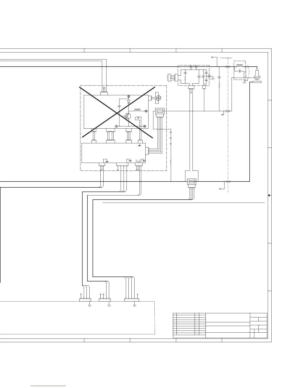
PILOT REG.
(CHOPPER )
PCB1
WK-5750
BIAS
POWER
PILOT REGULATOR
(CHOPPER)
< /OVER_TEMP
> P_DEM (P_Iref)
> P_Enable (P_ena)
PILOT REG.
(CHOPPER )
PCB2
WK-5754
I_DET
I_SE
<
<
PILOT CURRENT SIGNAL <
WORK CURRENT SIGNAL <
/PILOT ENABLE >
PILOT DEMAND >
HCT1 Hall Current Sensor, Pilot (B8, Sht 1)
HCT2 Hall Current Sensor, Work (C9, Sht 1)
L1,L9 Toroid Core input common mode filter (A2, B2, Sht 1)
L2-7 Toroid Core common mode filter (B1, C1, Sht 1)
L8,L10 Toroid Core output common mode filter (A6, C6, Sht 1)
LSW1 Level SW, coolant, NC (B5, Sht 2)
MC1 Contactor, 3P ,Inv 1 input, Coil (B3, Sht 2)
" Contacts (A2, B2, Sht 1)
" Aux Contact (B3, Sht 2)
MC2 Contactor, pilot, Coil (B3, Sht 2)
" Contacts (B8, Sht 1)
MC3 Contactor, 3P ,Inv 2 input, Coil (B3, Sht 2)
" Contacts (B2,C2, Sht 1)
" Aux Contact (B3, Sht 2)
MOT1 Motor, Pump 200VAC, 1P (E4, Sht 2)
NE1 Neon indicator, rear panel, 220VAC (C1, Sht 1)
NE2 Neon indicator, internal, 220VAC (D1, Sht 1)
NFC1 & 2 Noise Filter, EMI, input (A3, B3, Sht 1)
R1 Resistor, Pilot, 4 Ohm, 1 KW (C8, Sht 1)
R6 Resistor, 20K ,30W (A8, Sht 1)
R7 Resistor, 1K ,30W (E2, Sht 2)
R9 Resistor, 50 ,40W (A9, Sht 1)
T1 Aux Transformer (D-F1, Sht 2)
TH1 Thermal Sensor, coolant return (B5, Sht 2)
COMPONENT LOCATOR
(C7, Sht 2)
Power Supply
Rear Panel
DAT
For this version of the power supply
Pilot Regulator is not used except to
provide power and pass signals
from HCT1, the pilot current sensor.
A Pilot Resistor, R1, is used instead.
ECO-B402 DAT 2/26/07
AB
C1 Capacitor, 0.1 uf, 1250 VDC (D2, Sht 2)
C2 Capacitor, 2 uf, 430VAC (A9, Sht 1)
C.P1 Circuit protector/ON-OFF SW (B2, Sht 1)
15A, 460V, 3P
C.P2 Circuit protector 2.5A 125V (D2, Sht 1)
C.P3 Circuit protector 3.15A 125V (D2, Sht 1)
C.P4 Circuit protector 10A 125V (E2, Sht 1)
C.P5 Circuit protector 2.5A 125V (E2, Sht 1)
C.P6 Circuit protector 2.5A 125V (F2, Sht 1)
C.P7 Circuit protector 5A 125V (E2, Sht 1)
C.P8 Circuit protector 3.15A 125V (F3, Sht 1)
D1 Diode Bridge 20A, 1600V, 3P (D2, Sht 1)
FAN1 Fan, Coolant, 24 VDC (F4, Sht 2)
FAN3 Fan, Chopper, 24 VDC (A8, Sht 1)
FL1 Flow sensor (B5, Sht 2)
ECO-B448 DAT 4/13/07
(C7 & A9,Sht 2)
(C7 & A9,Sht 2)
ECO-B646 GAC 10/31/07AC
CN2CN2
1
2
3
4
HCT2HCT2
1
2
3
4
CN4CN4
1
2
3
TB1TB1
TB2TB2
TB5TB5
TB1TB1
CN2CN2
1
2
3
R1
4 Ohm 1KW
R1
4 Ohm 1KW
HCT1HCT1
1
2
3
4
TB2TB2
WORKWORK
CN1CN1
1
2
CN5CN5
1
2
3
4
CN5CN5
1
2
3
4
CN2CN2
1
2
3
CN3CN3
1
CN33CN33
1
2
3
4
CN3CN3
1
2
MC2-AMC2-A
TB4TB4
CN4CN4
1
2
3
4
5
MC2-BMC2-B
MC2-CMC2-C
CN1CN1
1
2
3
4
CN4CN4
1
2
3
4
5
CN7CN7
1
2
3
4
5
CN1CN1
1
2
3
4
CN6CN6
1
2
3
THS1
SW_TEMP_NC
THS1
SW_TEMP_NC
R6
20K
30W
R6
20K
30W
TB3TB3
CN8CN8
1
2
C2
2 UF
C2
2 UF
CN9CN9
1
2
R9
50
R9
50
FAN3FAN3
+ -
CN3CN3
1
2
3
4
Art # A-07006_AB
 Loading...