Manual No. 0-4805 Auto-Cut 200 3-3 INSTALLATION
G
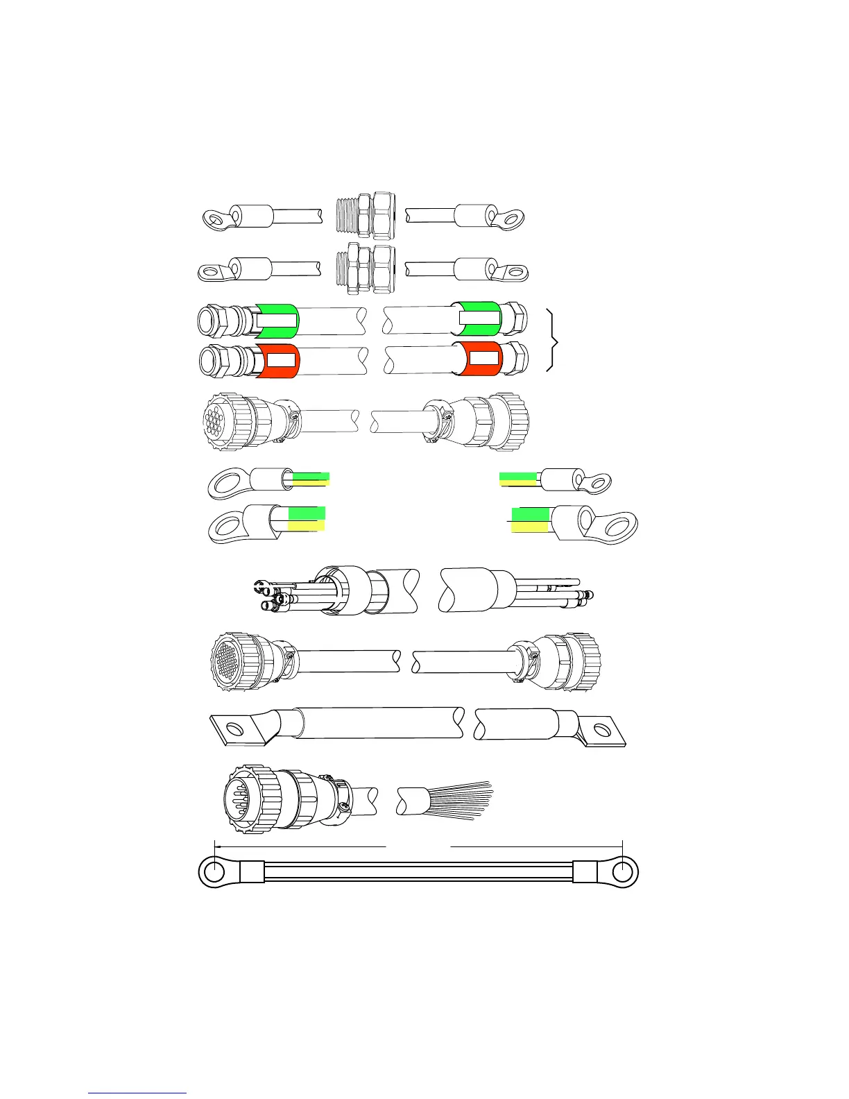
Torch Lead Set
Art # A-07103
Green / Yellow #10 AWG
Green / Yellow 1/0 (50 mm )
A
Green
Red
#8 AWG Cable
#1 AWG Cable
B
C
D
E
F
F1
K
Work Cable
CNC Cable (14 Wire)
37
14
Coolant Leads, Power Supply
to Arc Starter
1/0 (50 mm ) Cable
Pilot Return, Power Supply
to Arc Starter
Negative Lead, Power Supply
to Arc Starter
Control Cable, Power Supply
to Arc Starter
Ground Cable
Ground Cable,
Arc Starter
To Earth Ground
O
P
Control Cable,
Power Supply to
Gas Control Module
Green
Red
2
2
Q
4’ / 1.3 m
Ground Cable, Gas Control Module
to Power Supply. Factory Installed.
#4 AWG
3.03 Cables & Leads Identification
 Loading...