Electrical Maintenance
55
Battery
NOTE: The Microprocessor Power switch must
be placed in the Off position before connecting
or disconnecting the battery terminals. The
Microprocessor Power switch is located on the
control box side of the unit.
Inspect/clean the battery terminals and check the
electrolyte level during scheduled maintenance
inspections. A dead or low battery can be the
cause of an ammeter indicating discharge due to
lack of initial excitation of the alternator even
after the unit has been boosted for starting. The
minimum specific gravity should be 1.235. Add
distilled water as necessary to maintain the proper
water level.
Unit Wiring
Inspect the unit wiring and the wire harnesses
during scheduled maintenance inspections for
loose, chafed or broken wires to protect against
unit malfunctions due to open or short circuits.
Electrical Contacts
Inspect all relay contacts for pitting or corrosion
every 1,000 operating hours, and repair or replace
as necessary.
Charging System (12 Vdc)
Immediately after start-up, the voltmeter may
show a low voltage condition on systems with
brush type alternators. This is due to a light film
build-up on the alternator slip rings. The film
build-up occurs primarily on units that have been
sitting unused for long periods of time. The film
should disappear after a minute or two, and the
voltmeter should show a high voltage that will
continue until the battery voltage is brought back
up to normal. If the voltmeter shows low voltage
after start-up, check the alternator belt tension and
all charging circuit connections including the
battery.
NOTE: On installations where the unit is
connected to the truck battery and both units are
running—it is normal for the unit to indicate a
discharge condition while the truck engine is
running because of the truck’s higher voltage
charge rate.
Preheat Buzzer
The preheat buzzer module on the circuit board is
designed to indicate preheat is in operation.
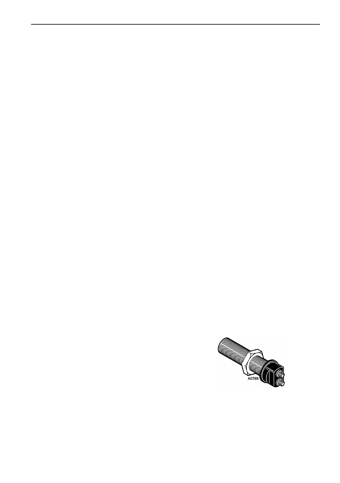
RPM Sensor
The RPM sensor is in the engine bell housing
adjacent to, but not touching, the flywheel
(backed off 1/2 turn).
The RPM sensor is a device containing an
inductance coil and magnet. When the magnetic
field is distorted by the passing ring gear teeth, the
inductance coil generates an ac electrical signal
that has a voltage and frequency variation
proportional to the engine RPM.
By monitoring the frequency of this signal with
the µP-T, the timing of the starter disengagement
can be precisely controlled.
If the RPM sensor fails, the starter may not
disengage or engage properly and a fault code will
be generated to the microprocessor.
Testing the RPM Sensor:
The following equipment is required:
• AC voltmeter capable of reading up to 10
volts
• Ohmmeter
The flywheel (RPM) sensor may be checked as
follows:
1. Install the flywheel (RPM) sensor into the
flywheel; bracket of the start-stop unit until it
contacts the ring gear. Back out the sensor 1/2
turn and tighten the locknut.
Figure 25: Flywheel (RPM) Sensor
 Loading...