19
Parker Hannifin Corporation
Tube Fittings Division
Columbus, OH
FluidConnectors
Bulletin 4390-974250
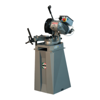
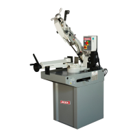
Cut 250 Saw Use and Maintenance Manual
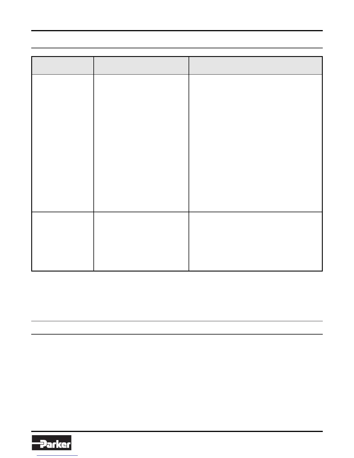
12.2 — Electrical components diagnosis
FAULT PROBABLE CAUSE REMEDY
Change it.
Check: • Phases
• Cables
• Socket
• Plug
Voltage must arrive upstream from the fuses.
Check for efficiency.
Identify and eliminate.
It must be turned to position 1 or 2.
Ensure that it is off and that its contacts are unbroken.
Check mechanical efficiency.
Check current continuity on the two wires in the prone after
letting the motor cool for about 10-15 minutes. If after this
time there is no current continuity in the two wires, the motor
must be changed or rewound.
Check that the supply voltage is the same as the line voltage
and that it gives a value of 24 V at output.
Check fuse efficiency and ensure there are no short circuits
causing the protection to trip.
Check that 24 V reach the coil terminals when the button
“SB 2” is pressed. If this happens and the relay is not self-fed,
it must be changed.
MOTOR STOPPED
WITH PILOT LIGHT
“HL” LIT
Socket and plug connecting the electric
box/microswitch in the handle
Microswitch “SQ 1” in the handle
Remote-control switch “KM”
Motor “M 1”
Check that the plug is correctly inserted and look for any bad
connections inside the box.
Check operation and/or efficiency. Replace if broken.
Check that phases are present at both input and ouput.
Ensure that it is not blodked, that it closes when fed, that it
does not cause short circuits. Otherwise change it.
Check that it is not burnt and that it turns freely.
It may be rewound or changed.
THE GREEN PILOT
LIGHT “HL” DOES NOT
LIGHT UP
Fused lamp
Power supply
Fuses “FU 1”
Short circuits
Speed switch “SA” in position “0”
Emergency button “SB 1” on
Cycle reset or line button “SB 2”
Thermal probe built into the stator winding
has tripped due to motor overheating
Transformer “TC 1”
Fuse “FU 2”
Auxilliary relay “KA”
13
Noise Tests
In accordance with point 1.7.4.f of the Machines Directive EEC 89/392.
INTEGRATING PHONOMETER “DELTA OHM” mod. HD9019K1 serial n. 110996B295.
MICROPHONE mod. HD 9019S1.
SOUND GAUGER mod. HD 9101at 94dB/110dB a 1.000 Hz in class 1 according to IEC regulation n. 942 1988 and ANSI S1.40
1984.
3 measurements with the machine operating unloaded.
• The microphone was been located close to the operator’s head, at medium height.
• The weighted equivalent continuous acoustic pressure level was 77.6 dB (A).
• The maximum level of the WEIGHTED instantaneous acoustic pressure C was always less than 130 dB.
NOTE: With the machine operating, the noise level will vary according to the different materials being processed. The user must
therefore assess the intensity and if necessary provide the operators with the necessary personal protection, as required by
Law 277/1991.