5
Parker Hannifin Corporation
Tube Fittings Division
Columbus, OH
FluidConnectors
Bulletin 4390-974250
Cut 250 Saw Use and Maintenance Manual
4.3 — Minimum requirements for the premises
housing the machine
• Main voltage and frequency complying with the machine mo-
tor characteristics.
• Environment temperature from -10°C to +50°C.
• Relative humidity not over 90%.
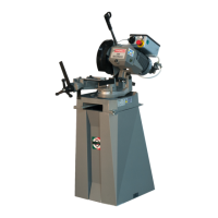
4.4 — Anchoring the machine
• Position the machine base on a firm cement floor, maintain-
ing, at the rear, a minimum distance of 800 mm from the
wall; anchor it to the ground as shown in the diagram, using
screws and expansion plugs or tie rods sunk in cement, en-
suring that it is sitting level.
4.5 — Instructions for electrical connection
• The machine may not be provided with an electric plug.
1 – WIRING DIAGRAM FOR 5-WIRE SYSTEM WITH NEU-
TRAL FOR THREE-PHASE MACHINE - SOCKET FOR A
16A PLUG
2 – WIRING DIAGRAM FOR THE SINGLE-PHASE SYSTEM
SOCKET FOR A 16A PLUG
PEDESTAL PROFILE
580
7070
440
270 290
560
AA
SEC. A - A
M8
12
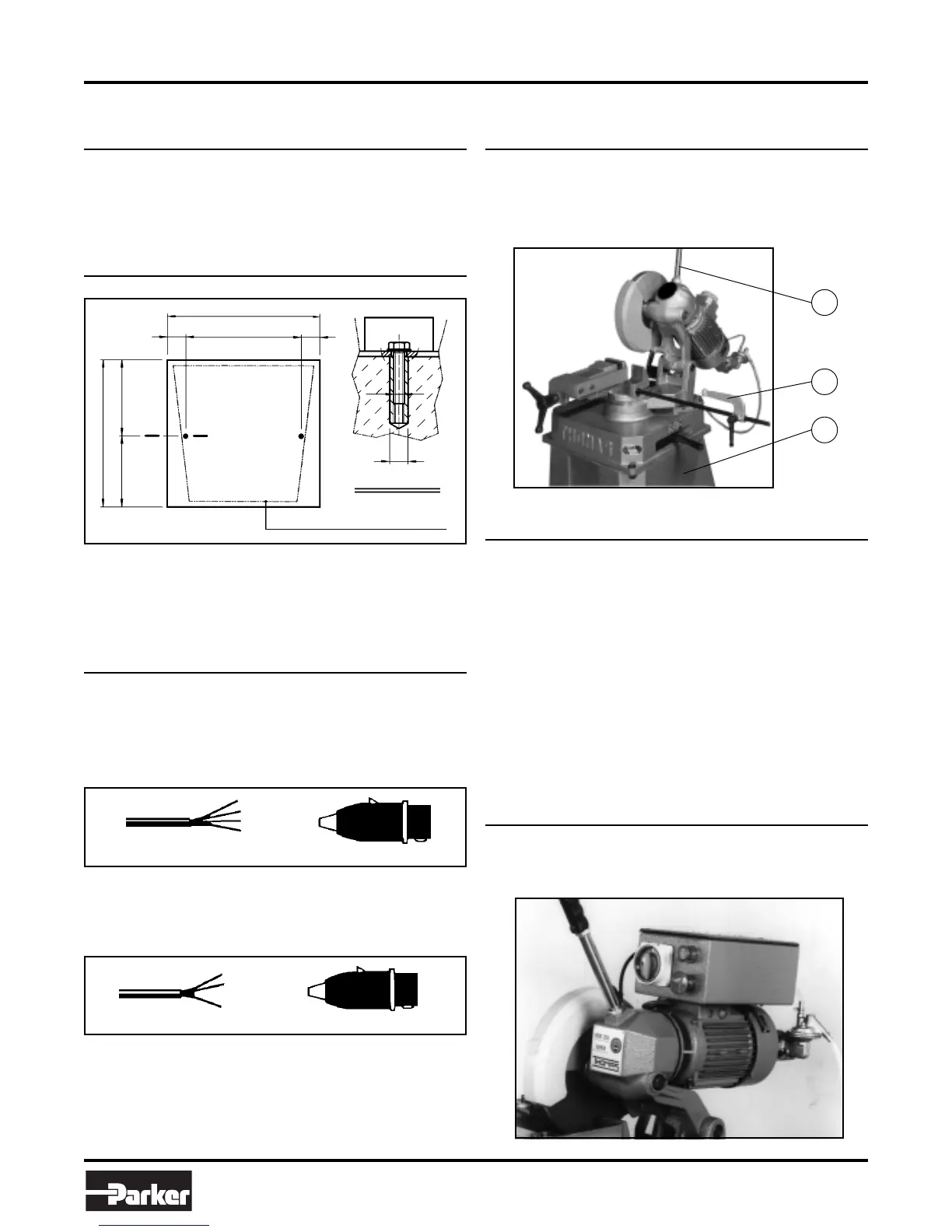
4.6 — Instructions for assembly of the loose
parts and accessories
Attach the components supplied as indicated in the photo:
• part. 1 Screw the lever onto the head
• part. 2 Attach the bar holding rod
• part. 3 Attach the pedestal firmly onto the base
4.7 — Deactivating the machine
If the sawing machine is not to be used for a long period, it is
advisable to proceed as follows:
1) Detach the plug from the electric supply panel
2) Release the head return spring
3) Empty the coolant tank
4) Carefully clean and grease the machine
5) If necessary, cover the machine.
5
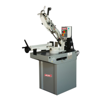
Machine Functional Parts
5.1 — Operating head
• Machine part composed of the parts that transmit move-
ment (motor, reduction unit), the lubricating coolant pump
and the electrical components.
= L1
= L2
= PE
R = L1
S = L2
T = L3
PE = GND
N = NEUTRAL
2
1
3