Silicon Image
Confidential for Philips
Consumer Electronics
Internal Use Only
SiI9185A 3:1 HDMI 1.3 Switch
Preliminary Data Sheet
Silicon Image, Inc.
Block Level Functionality
The SiI9185A 3:1 HDMI 1.3 switch is used to select a single set of HDMI/DVI signals from one of three HDMI/DVI
receiver-ports, and to generate a fully compliant HDMI/DVI stream as an output. It also provides DDC/HDCP, HPD,
and +5V switching to allow full compliance to the HDMI/DVI specifications.
The combination of dynamic equalizer and state-of-the-art DPLL can overcome signal distortion due to the long lengths
of HDMI/DVI cables. SiI9185A-based switches can be cascaded many times to regenerate TMDS and HDCP signals.
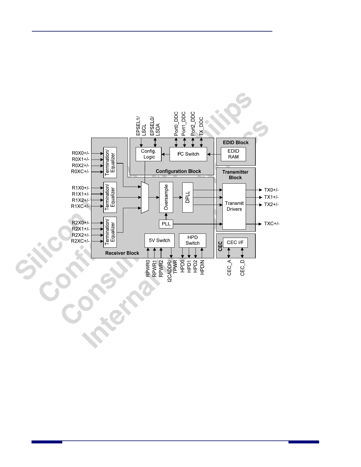
Figure 4. Functional Block Diagram
As shown in Figure 4, the SiI9185A consists of five major blocks:
• Receiver block
• Transmitter block
• CEC Interface block
• EDID RAM block
• Configuration block
Receiver Block
The three HDMI/ DVI receive ports are defined as Port 0, Port 1, and Port 2. Each of the ports is terminated separately
and equalized under the control of the receiver digital block and controlled by the local I
2
C bus. Port 0, Port 1, Port 2, or
power down of all ports are selected by using the Port Select (PSEL[1:0]) signals. PSEL[1:0] can either be controlled by
a register in I
2
C mode, or pins in stand-alone mode.
The I
2
C Switch conveys bidirectional DDC/EDID and HDCP information. In order to comply with the HDMI/DVI and
HDCP specifications, the SiI9185A also switches and relays information with correct timing from three bidirectional I
2
C
Rx-ports to one bidirectional Tx-port. The HDCP switching and relaying operation is also done in the Receive block by
monitoring the I
2
C/HDCP protocol to decide the right direction of signal transfer. The port selection signal is used to
provide correct HDCP data flow between the selected Receiver and the Transmitter port.
6 © 2007 Silicon Image, Inc. CONFIDENTIAL SiI-DS-1016-0.80