Silicon Image
Confidential for Philips
Consumer Electronics
Internal Use Only
SiI9185A 3:1 HDMI 1.3 Switch
Preliminary Data Sheet
Silicon Image, Inc.
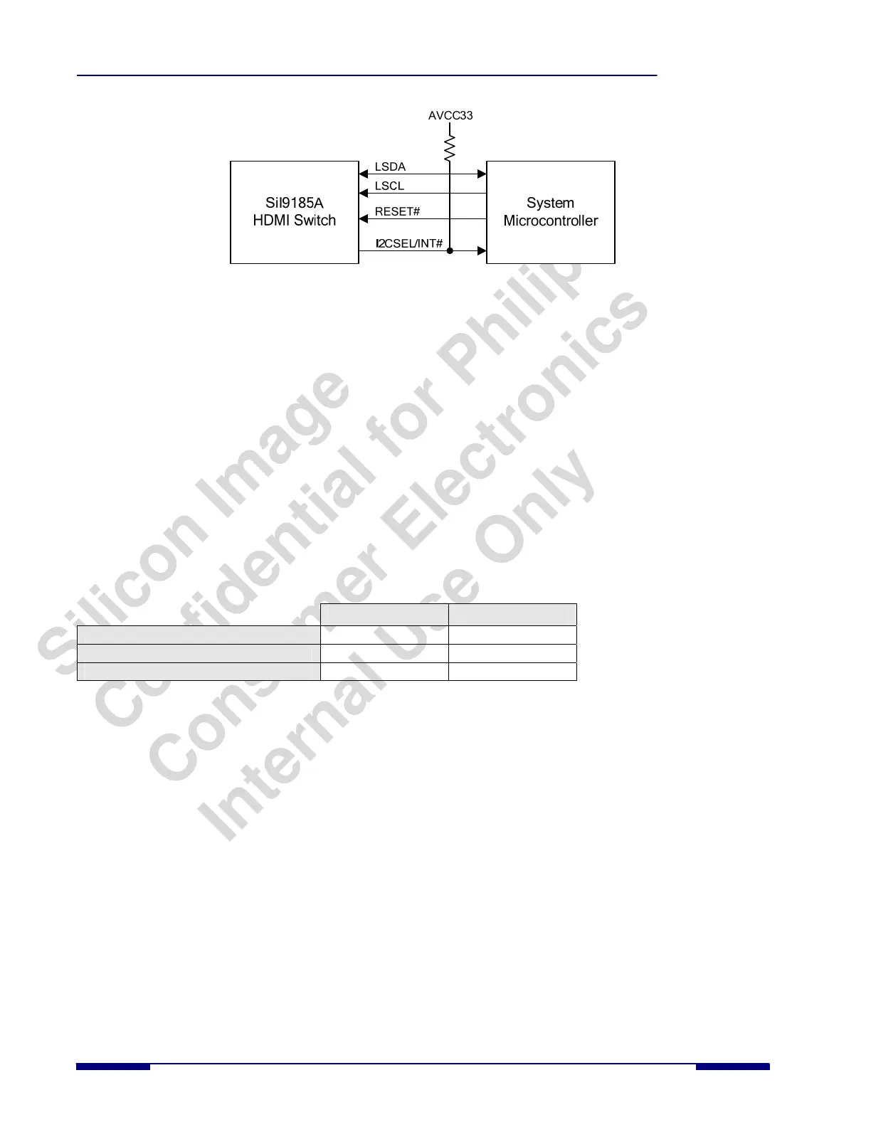
Figure 6. I
2
C Control Mode Configuration
I
2
C Interfaces
There are five I
2
C interfaces in the SiI9185A. There is one local slave I
2
C port that is used to configure the operation of
the SiI9185A in I
2
C mode. Three slaves are connected to the three DDC receive ports, and one master is connected to the
DDC transmit port; these ports are used to transfer DDC and HDPC information. All of the I
2
C pads are 5V tolerant and
compliant to the I
2
C specification.
Local Slave I
2
C Interface
The local I
2
C interface on the SiI9185A (pins LSCL and LSDA) is a slave interface capable of running up to 100 kHz.
This bus is used to configure the SiI9185A by reading/writing to necessary registers.
The local I
2
C interface of the SiI9185A consists of three separate I
2
C slave addresses. This means the SiI9185A will
appear as three separate devices on the I
2
C local bus. The first of these addresses is used for PHY and Chip Control
registers, is fixed, and can only be set to one of two values by using the I2CADDR pin. The other two addresses (used
for CEC and EDID) have an I
2
C register programmable address mapped into the PHY and Chip Control register space,
so the default value can be changed if there is a bus conflict with another device.
Table 1. Control of the Default I
2
C Addresses with the I2CADDR Pin
I2CADDR=LOW I2CADDR=HIGH
PHY and Chip Control Registers (fixed)
0xD0 0xD4
EDID Controller (programmable)
0xE0 0xE4
CEC Registers (programmable)
0xC0 0xC4
The PHY and Chip Control I
2
C address is fixed at boot-up and cannot be changed. The EDID Controller I
2
C Address
and the CEC Controller I
2
C Address each have a register associated with them that allows the address to be changed. See
the SiI9181/9185 HDMI Switch Programmer’s Reference Guide for more information.
DDC Receiver Ports (Slave) and DDC Transmitter Port (Master) Interfaces
The DDC bus is an I
2
C interface used in the HDMI interconnection to facilitate bidirectional transfer of DDC/EDID
information and perform the HDCP authentication process between source and sink devices. The SiI9185A includes
three DDC slave I
2
C ports, one for each of the receive ports. These are used for direct connection to each of the upstream
HDMI transmitters. The SiI9185A also includes a master I
2
C port for direct connection to the downstream HDMI
receiver (Figure 3). The DDC ports support I
2
C transactions specified by the VESA Enhanced Display Data Channel
Standard and supports I
2
C transactions needed for HDCP.
The DDC master I
2
C port and the three DDC slave I
2
C ports comply with the Standard Mode timing of the I
2
C
specification (100 kHz). Due to the relaying function in the SiI9185A, the I
2
C master in the transmit port does not
support SCL clock stretching by the slave to which it is connected. This is not an issue when used in sink applications
that use Silicon Image receivers because they do not perform any clock stretching. For other applications it should be
confirmed that the sink receiver device that connects to the SiI9185A output does not perform clock stretching on the I
2
C
bus. For source applications an external I
2
C switch (such as the NXP 9545A) can be used to bypass the master and slave
DDC ports of the SiI9185A. This will eliminate the SCL clock stretching issue (see Figure 4).
The SiI9185A will operate between an HDMI source and sink device, so DDC/EDID and HDCP transactions on the
DDC bus must flow through the SiI9185A without causing information loss or timing margin degradation. The SiI9185A
8 © 2007 Silicon Image, Inc. CONFIDENTIAL SiI-DS-1016-0.80