Conceptual
3
DS8110-01C March 2007 www.richtek.com
RT8110
Functional Pin Description
Pin No. Pin Name Pin Function
1 BOOT
This pin provides ground referenced bias voltage to the upper MOSFET driver. A bootstrap
circuit is used to create a voltage suitable to drive a logic-level N-MOSFET when operating
at a single 5V power supply.
2 DRIVE
This pin connects to the base of the external BJT(2N2222), which is designed to withstand
to 23V and provides a regulated 5.3V voltage to VCC pin as the power of the PWM
controller. The pin also can function as shut down with two different application circuits. The
one can pull low the pin to gnd, the other can pull low drive to make V
DD
lower than POR
threshold.
3 FB
This pin is connected to the PWM controller’s output divider. This pin also connects to
internal PWM error amplifier inverting input and protection monitor.
4 VCC
This is the main bias supply for the RT8110. This pin also provides the gate bias charge for
the lower MOSFET gate. The voltage at this pin is monitored for power-on reset (POR)
purpose.
5 LGATE
Connect LGATE to the PWM controller’s lower MOSFET gate. This pin provides the gate
drive for the lower MOSFET.
6
GND Signal and power ground for the IC. All voltage levels are measured with respect to this pin.
7 UGATE
Connect UGATE pin to the PW M controller’s upper MOSFET gate. This pin provides the
gate drive for the upper MOSFET.
8 PHASE
This pin is used to monitor the voltage drop across the lower MOSFET for over-current
protection.
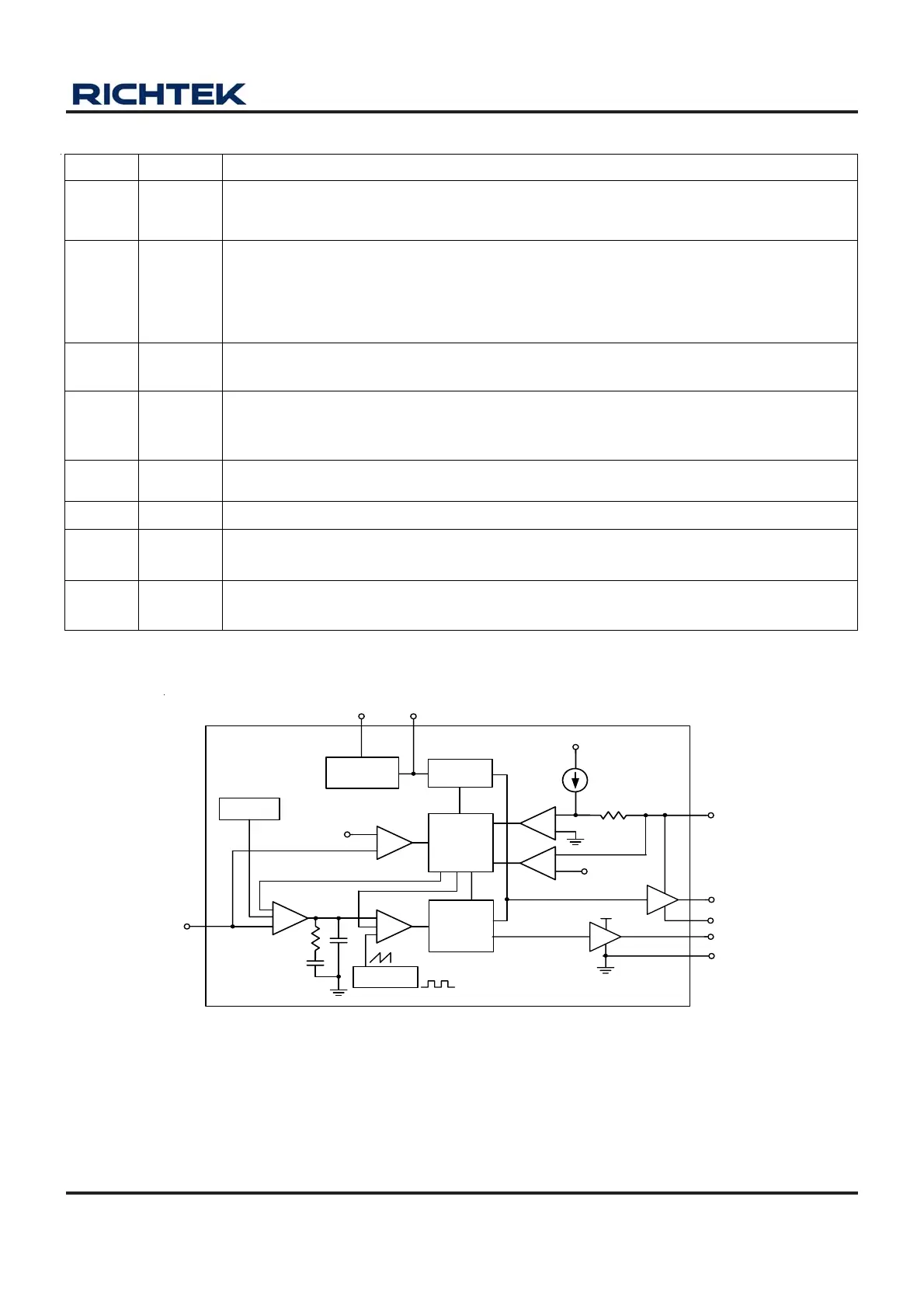
Function Block Diagram
Soft-Start
and Fault
Logic
Gate
Control
Logic
+
-
+
-
VCC
R
OC
I
OC
1.5V
BOOT
FB
VCC
PHASE
GND
LGATE
DRIVE
UGATE
VCC
Power-
On Reset
POR
+
-
0.5V
+
-
+
+
-
+
0.8V
REF
UVP
PWM
Gm
V
CC
Regulator
Oscillator
S1L
OC
PH_M
SSE
EO
SS