Silicon Image
Confidential for Philips
Consumer Electronics
Internal Use Only
SiI9185A 3:1 HDMI 1.3 Switch
Preliminary Data Sheet
Silicon Image, Inc.
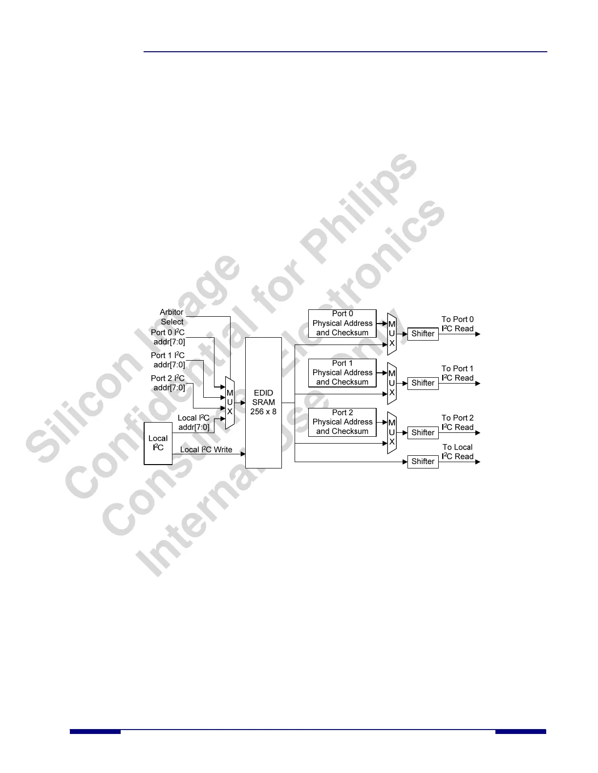
EDID Emulation Function Using RAM
The EDID is stored in 256 bytes of on-chip RAM. The SiI9185A contains I
2
C distributor/arbiter logic to ensure that the
EDID can be read by all three DDC input buses simultaneously.
The EDID memory provides identical information to each DDC channel except for the following:
• The CEC physical address for each channel. The location of this physical address in the EDID memory is
specified by the contents of the CSCPA_ADDR register (0xE0:0x08) in the EDID controller. When the EDID
memory is loaded through the local I
2
C controller, the CEC physical address contains the value for Channel
(Port) 0. When the EDID controller detects that DDC for Channel 1 or Channel 2 is trying to read the CEC
physical address location, it automatically replaces the information with the actual CEC1 or CEC2 physical
address values stored in the CEC Physical Channel Address registers.
• Checksum. The checksum is always stored in the last register address for the EDID space (location 0xFF).
When the EDID memory is loaded through the local I
2
C controller, the checksum value (location 0xFF)
contains the value for Channel (Port) 0. However, the checksum is different for each channel due to the
difference in physical CEC addresses for these channels. The host firmware stores different checksums for
channels 1 and 2 in two different locations in the EDID controller registers. When the EDID controller logic
detects that the DDC for a particular channel is reading the checksum, it responds with the value in one of the
two registers, based on the inquiring port.
Figure 8 shows a block diagram of how the EDID function is emulated using RAM.
Figure 8. EDID Emulation Using RAM
The EDID contains the CEC physical address and must be loaded before enabling the CEC function. Additionally,
HOTPLUG must be controlled to guarantee proper EDID and CEC operation by the host. The basic flow for loading the
EDID into SiI9185A is shown below:
1. Power up the system.
2. Reset the SiI9185A.
3. Load the EDID for Port 0 into the SiI9185A.
4. Write the CEC physical addresses for Port 1 and Port 2.
5. Write the checksum values for Port 1 and Port 2.
6. Calibrate the CEC clock if using the CEC API.
7. Initialize the CEC registers if using the CEC API.
8. Enable DDC and CEC for all ports.
9. Write the registers to set HPD0, HPD1, and HPD2 high (now the host can read the EDID).
SiI-DS-1016-0.80 © 2007 Silicon Image, Inc. CONFIDENTIAL 13