Silicon Image
Confidential for Philips
Consumer Electronics
Internal Use Only
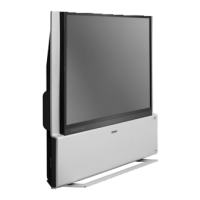
SiI9185A 3:1 HDMI 1.3 Switch
Preliminary Data Sheet
Silicon Image, Inc.
analyzes and regenerates the DDC signal, making it possible to extend the cable length of I
2
C DDC by cascading
multiple SiI9185As together.
Control Pins
The SiI9185A can operate in two distinct modes, depending on the state of the I2CSEL pin at the end of RESET#:
Standalone mode, and I
2
C Control mode. In Standalone mode, the SiI9185A operates independently and has no need for
an external microprocessor. The configuration of the switch is set using signals on the external control pins listed below,
and after configuration, the switch operates independently.
In I
2
C Control mode, the SiI9185A requires an external processor and is controlled over the I
2
C interface.
RESET# Control Pin
The system reset pin (RESET#) is an active-low input. When RESET# is low, all digital logic is reset including the I
2
C
interfaces. When RESET# is high, the SiI9185A operates in normal mode.
Two pins are used to configure bootstrap options on the rising edge of RESET#: I2CSEL/INT and I2CADDR/TPWR.
The I2CSEL/INT is sampled on the rising edge of RESET# to determine the operating mode. The I2CADDR/TPWR pin
is sampled on the rising edge of RESET# to determine the base address of the I
2
C interface. These pins are discussed in
the sections that follow.
I2CSEL/INT
The dual-purpose I2CSEL/INT pin acts as a configuration input pin for mode selection during the period when RESET#
is true (low), and as the interrupt (INT) output during normal operation. The level on the I2CSEL/INT pin is latched
when the RESET# signal transitions from low to high. If the I2CSEL/INT value is high on the rising edge of RESET#,
the SiI9185A comes up in I
2
C Control mode. If the I2CSEL/INT value is low at the rising edge of RESET#, the
SiI9185A comes up in Standalone mode and the EPSEL[1:0] pins are used as the external port select pins. Note that
when I2CSEL is low at the rising edge of RESET#, the local I
2
C is disabled from that time, but the contents of the local
I
2
C registers are not lost.
After RESET# is deasserted (goes high), the I2CSEL/INT pin becomes the interrupt output pin (INT). When interrupt
conditions are met and the particular interrupt is enabled, the INT signal goes low indicating to the host that an interrupt
has occurred and that actions are needed.
EPSEL1/LSCL and EPSEL0/LSDA
The EPSEL1/LSCL and EPSEL0/LSDA pins are dual-function pins, and their function depends on whether the
SiI9185A is in Standalone mode or in I
2
C Control mode. In Standalone mode, these pins become the external port
selection pins EPSEL[1:0]. In I
2
C Control mode, the EPSEL1/LSCL becomes the I
2
C Interface clock signal LSCL, and
the EPSEL0/LSDA pin becomes the I
2
C Data signal LSDA.
The receive port is selected externally using the EPSEL[1:0] pins in Standalone mode, or internally using I
2
C registers
(I
2
C Control mode). When I2CSEL is high at the end of RESET#, the receive port is selected by the I
2
C register
IPSEL[1:0] (0xD0: 0x08). When I2CSEL is low at the end of RESET#, the receive port is selected using the external
pins EPSEL[1:0] as shown in Table 1, and the local I
2
C interface is disabled.
Table 2. Port Selection Using the EPSEL Pins
EPSEL1 EPSEL0
Port 0
0 0
Port 1
0 1
Port 2
1 0
Standby Mode
1 1
SiI-DS-1016-0.80 © 2007 Silicon Image, Inc. CONFIDENTIAL 9