YOUR RECEIVER
P5
2.0 YOUR RECEIVER
2.1 PIN code default: 0000
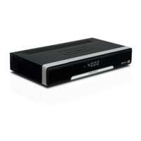
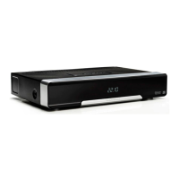
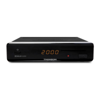
2.2 Front and side panel
Fig. 1
1. Power button: Switch the receiver to Standby or On.
2. P-/P+: To change channels without using the remote control
3. Remote control sensor:
Receives the signal from the remote control
4. LED display: Shows channel number in operation and time in Standby
5. Standby indicator:
Shows power state of the receiver: Red LED - receiver is in
standby mode
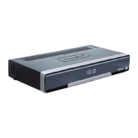
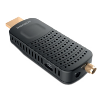
2.3 Rear panel
Fig. 2
1. SAT IN To connect to the LNB of your satellite dish for reception of
satellite broadcast signal
2. Ethernet To connect to a network switch, router or modem
3. USB For connection of USB device for Multimedia use
4. HDMI To connect to the HDMI input of your TV using a good quality
HDMI cable
5. TV SCART To connect to TV using a SCART cable
6. Audio L/R To connect to an analogue amplifier for stereo audio
7. S/PDIF coaxial To connect to a digital or home cinema audio amplifier
8. Power connector The receiver requires a wall adapter, mains voltage input
100~240V AC 50~60Hz 12V, 1.5A DC output. Please check the
local power conditions before connecting the receiver to the
mains supply.
2.4 Remote Control
Fig. 3
1. q Switches the receiver On/Standby
2. ! To turn the sound on or off
3. FAV To access your favourite channels. Toggles between available
favourite groups
4. LIST Shows the recording list*
5. AUDIO Displays the audio selection menu with selections for available
languages and audio modes
6. 9 To switch between the last viewed channels
7. RED Flexible functions in OSD menu and Teletext
8. GREEN Flexible functions in OSD menu and Teletext.

 Loading...