Owner’s Manual
E2010 THYSSENKRUPP ELEVATOR Printed in USA February, 2010
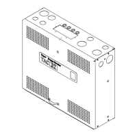
Door Operator-5
The following is a list of the major components of a Door Operator. See Figure 1. (It includes a description of their functions, overview
of some of the critical adjustments and maintenance information. See Installation and Maintenance for details.)
S Adjustable Arm - Thearmmountedtothedrivewheel.
Used to change the amount of linear door movement or
stroke.
S Connecting Arm - Connects the drive arm to the door pan-
el.
S Door Operator Support - A metal plate welded to the
header. The Door Operator is mounted to the Door Opera-
tor Support with (4) four bolts through the (4) mounting
slots of the Door Operator.
S Drive Arm - The linkage connected between the drive arm
support and the connecting arm.
S Drive Arm Support - The bracket on top of the door opera-
tor containing two holes. The drive arm should be con-
nected to the right hand hole, as you look from the hatch,
at the front of the door operator.
S Drive Wheel - A metal sheave containing a slotted cam
surface. The adjustable arm mounts to the drive wheel and
is adjusted in the slotted cam surface. The drive wheel is
driven by the jack shaft sheave using 3 V belts. Adjustment
of the linear door travel or stroke is accomplished by mov-
ing the adjustable arm. Moving the adjustable arm closer
to the center of the drive wheel results in less door travel for
the same amount of wheel rotation. Moving the adjustable
arm toward the outside of the drive wheel results in more
door travel for the same amount of wheel rotation.
S Idler Arm - An adjustable arm mounted to the front of the
door operator which controls the tension of the 3 V belts be-
tween the jack shaft sheave and the drive wheel.
S Intermediate Arm - Adjustable linkage connected be-
tween the drive wheel adjustable arm and the pivot arm.
The connection at the pivot arm is adjustable to control the
length of the intermediate arm.
S Mechanical Stops - Metal L brackets mounted to the front
of the door operator. The stops have slots to adjust the
amount of drive wheel rotation. Once positioned they limit
the physical rotation of the drive wheel.
S Motor - 115V or 230V DC Motor
S Pivot Arm - Connects the drive arm to the intermediate
arm. Provides an adjustment for the length of the inter-
mediate arm.
S Sheave, Jack Shaft - A spok ed sheave driven by the door
operator motor with a single V belt. The motor sheave
drives the jack shaft sheave which drives the drive wheel.
S Sheave, Motor - A sheave attached directly to the door
operator motor shaft.
S Support Strut -Unistrut legs on the rear of the door opera-
tor. Used to secure the rear of the operator to the car top
andtoplumbthefaceofthedrivewheel.