149
NC2 0 - Manual - 01 - 2015
INSTALLATION
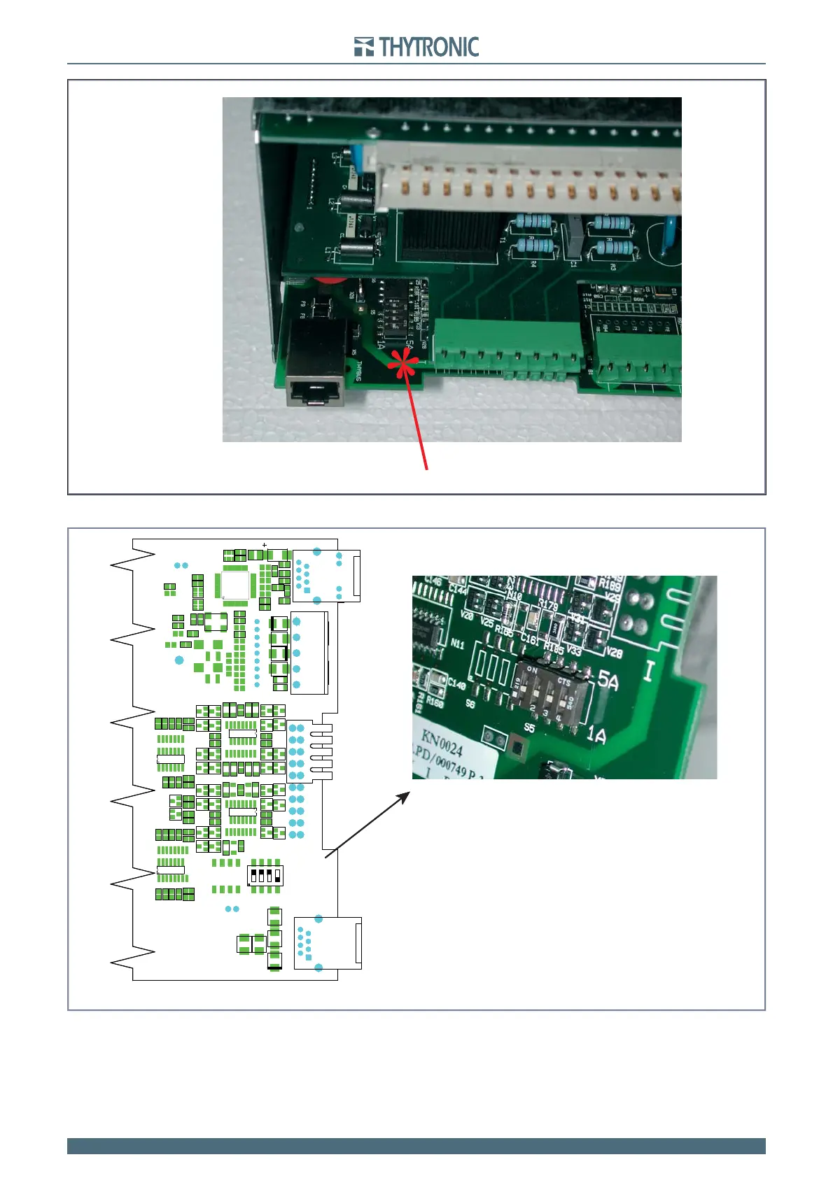
Move dip-switches according the following layout.
Reassemble all parts with the previous operations in reverse order.
Reconnect the RS485 and RJ45 cables (Ethernet and/or Thybus).
•
•
•
Dip-switch setting inside the CPU board
F
acory defaul settings:
- I
n
=5 A (phase currents)
- I
Nn
=1 A (unbalanced neutral current)
set-in.ai
ETHERNET
THYBUS
1 A
5 A
S5
485
1 234
IL1
IL2
IL3
IN
Dip-switch setting inside the CPU board
Facory defaul settings:
- I
n
=5 A (phase currents)
- I
Nn
=1 A (unbalanced neutral current)
set-in.ai
ETHERNET
THYBUS
1 A
5 A
S5
485
1 234
IL1
IL2
IL3
IN
set-in-0.ai
Dip-switch Localization concerning the nominal current setting inside the CPU board