2
2
NC2 0 - Manual - 01 - 2015
T A B L E O F C O N T E N T S
TABLE OF CONTENTS
1 INTRODUCTION 5
Scope and liability ...........................................................................................................................................................................................5
Applicability ......................................................................................................................................................................................................5
Conformity ........................................................................................................................................................................................................5
Copyright ...........................................................................................................................................................................................................5
Warranty ...........................................................................................................................................................................................................5
Safety recommendations ...............................................................................................................................................................................5
Insulation tests ................................................................................................................................................................................................5
Product identification .....................................................................................................................................................................................6
Environment .....................................................................................................................................................................................................6
Graphical conventions ...................................................................................................................................................................................6
Glossary/definitions ........................................................................................................................................................................................6
2 GENERAL 10
Preface ........................................................................................................................................................................................................... 10
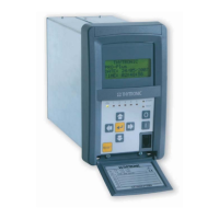
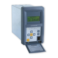
Photo .............................................................................................................................................................................................................. 10
Main features .................................................................................................................................................................................................11
3 TECHNICAL DATA 12
3.1 GENERAL ............................................................................................................................................................................................................12
Product standard for measuring relays .....................................................................................................................................................12
Mechanical data ...........................................................................................................................................................................................12
Insulation ........................................................................................................................................................................................................12
Voltage dip and interruption ........................................................................................................................................................................12
EMC tests for interference immunity .........................................................................................................................................................12
Emission ......................................................................................................................................................................................................... 13
Mechanical tests .......................................................................................................................................................................................... 13
Climatic tests ................................................................................................................................................................................................. 13
Safety ............................................................................................................................................................................................................. 13
Certifications ................................................................................................................................................................................................. 13
3.2 INPUT CIRCUITS ...............................................................................................................................................................................................14
Auxiliary power supply Uaux ......................................................................................................................................................................14
Phase current input circuits ........................................................................................................................................................................14
Unbalance neutral current input circuit ....................................................................................................................................................14
Voltage input circuits ....................................................................................................................................................................................14
Binary input circuits ......................................................................................................................................................................................14
3.3 OUTPUT CIRCUITS ............................................................................................................................................................................................14
Relays ..............................................................................................................................................................................................................14
Block output (Logic selectivity) ...................................................................................................................................................................14
3.4 MMI .....................................................................................................................................................................................................................15
3.5 COMMUNICATION INTERFACES ...................................................................................................................................................................15
Local port ........................................................................................................................................................................................................15
Remote ports ..................................................................................................................................................................................................15
3.6 GENERAL SETTINGS ........................................................................................................................................................................................16
3.7 PROTECTIVE FUNCTIONS ...............................................................................................................................................................................16
Base current - IB ...........................................................................................................................................................................................16
Discharge time - TD ......................................................................................................................................................................................16
Thermal protection with Pt100 probes - 26 ...............................................................................................................................................16
Undervoltage - 27 ..........................................................................................................................................................................................16
Undercurrent - 37 ..........................................................................................................................................................................................17
Phase unbalance - 46 ...................................................................................................................................................................................17
Neutral unbalance current - 46N ................................................................................................................................................................17
Thermal image - 49 ....................................................................................................................................................................................... 18
RMS Phase overcurrent - 50/51 ................................................................................................................................................................. 19
Phase overcurrent - 50/51 Fundamental .................................................................................................................................................. 20
Residual overcurrent - 50N/51N ................................................................................................................................................................ 20
Overvoltage - 59 .............................................................................................................................................................................................22
Breaker failure - BF .......................................................................................................................................................................................22
3.8 CONTROL AND MONITORING ....................................................................................................................................................................... 23
Trip Circuit Supervision - 74TCS ................................................................................................................................................................. 23
Selective block - BLOCK2 ........................................................................................................................................................................... 23
Circuit Breaker supervision ........................................................................................................................................................................ 23
CT supervision - 74CT .................................................................................................................................................................................. 23
Pilot wire diagnostic .................................................................................................................................................................................... 23
Demand measures ....................................................................................................................................................................................... 23