45
NC2 0 - Manual - 01 - 2015
FUNCTION CHARACTERISTICS
4.4 PROTECTIVE ELEMENTS
Rated values
Inside the Base menu the following parameters can be set:
Relay reference name.
Relay nominal currents (phase and residual), to which the regulation are related.
Primary nominal values, employed for measures relative to primary values.
Measurements reading mode.
Information for settings:
Relay reference name.
Alphanumeric mnemonic string (max 16 characters) useful for identifi cation of protected plant.
Relay nominal frequency f
n
This nominal value must be set same as the frequency of the grid.
Example: grid frequency f
n
= 50 Hz
Relay nominal frequency f
n
= 50 Hz
Relay phase nominal current I
n
This nominal value must be set by means dip-switch to 1 A or 5 A, same as the secondary CTs
nominal current.
Dip-switches are located on board of the CPU module; the exhaustive treatment of Dip setup is
described in the “6.5 SETTING NOMINAL CURRENTS I
n
AND I
En
” paragraph.
Relay unbalance nominal current I
Nn
This nominal value must be set by means dip-switch to 1 A or 5 A, same as the secondary CT nomi-
nal current.
Dip-switch is located on board of the CPU module; the exhaustive treatment of Dip setup is de-
scribed in the “6.5 SETTING NOMINAL CURRENTS I
n
AND I
Nn
” paragraph.
Relay nominal voltage U
n
The reference voltage is: U
R
=100 V
The U
n
relay nominal voltage must be set to the value of relay input voltages at grid nominal volt-
age.
The U
n
value must calculated as:
If VTs with primary nominal voltage is equal to the grid voltage divided by √3, the following stream-
lined calculus may be used:
U
n
= VTs secondary nominal voltage [V] x √3
Example 1
The relay nominal voltage may be set to:
U
n
= U
ng
/ √3 · K
TV
= 6000 /√3 · 60 = 100 /√3 = 58 V
•
•
•
•
•
•
•
•
•
Voltage transfotmer ratio K
VT
Grid nominal voltage U
ng
where the VTs are included [V]
U
n
=
Voltage transfotmer ratio K
VT
Grid nominal voltage U
ng
where the VTs are included [V]
U
n
=
Es1-Un.ai
K
TV
=
/
/
V
V
6000
3
100 3
= 60
U
ng
= 6.0 kV
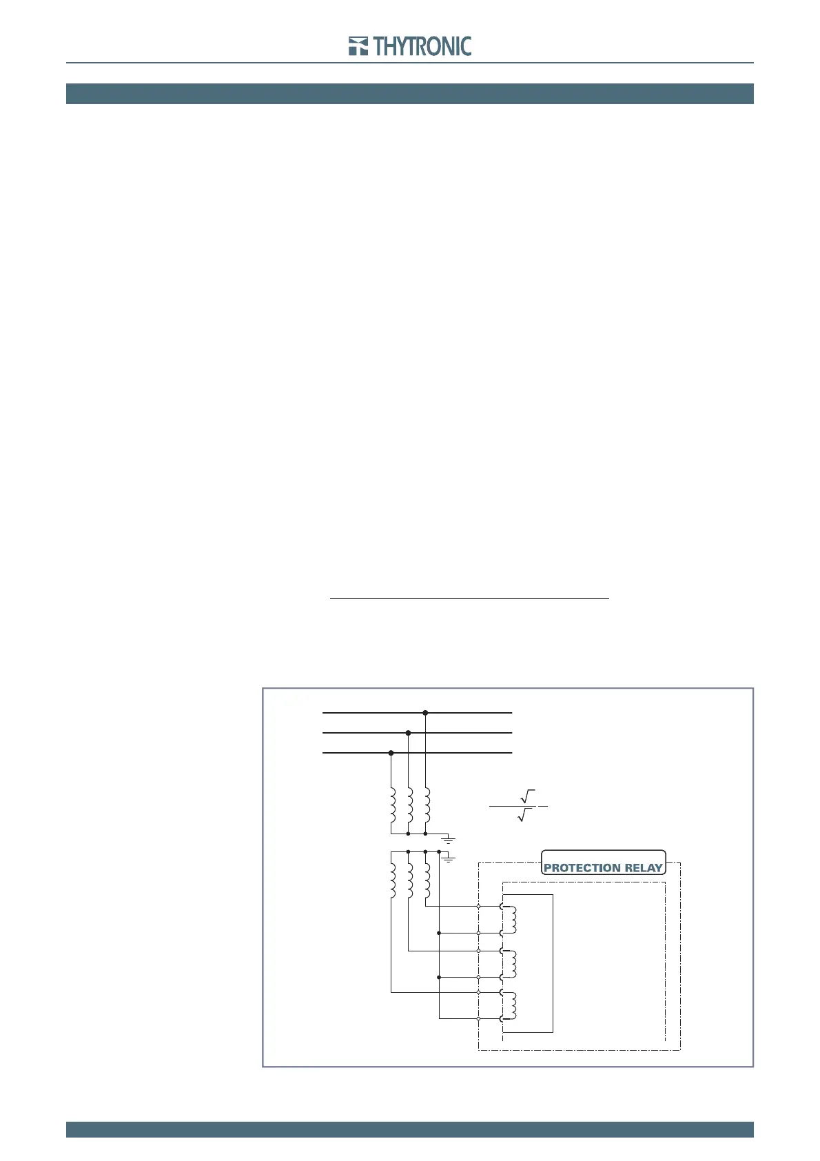
NC20
U
L1
U
L2
U
L3
VOLTAGE INPUTS
n
a
N
A
L1
L2
L3
B5
B6
B3
B4
B1
B2
Phase to ground VTs connection
Es1-Un.ai
K
TV
=
/
/
V
V
6000
3
100 3
= 60
U
ng
= 6.0 kV
NC20
U
L1
U
L2
U
L3
VOLTAGE INPUTS
n
a
N
A
L1
L2
L3
B5
B6
B3
B4
B1
B2
Phase to ground VTs connection