63
NC2 0 - Manual - 01 - 2015
FUNCTION CHARACTERISTICS
Neutral unbalance current - 46N
Preface
One alarm and two operation thresholds, independently adjustable (I
N>AL
, I
N>
, I
N>>
) with adjustable
operating times (t
N>AL
, t
N>
, t
N>>
).
The fi rst one is based on defi nite time characteristic.
The I
N
> operation threshold may be programmed with defi nite or inverse time according the IEC and
ANSI/IEEE standard; the second thresholds (I
N
>>) is based on defi nite time characteristic.
The fi rst alarm threshold may be inhibited by start of the operation thresholds ( I
N
>, I
N
>>); similarly
the fi rst threshold trip may be inhibited by start of the second threshold (I
N
>>).
Operation and settings
The unbalance current I
N
is used with:
Fundamental component of the neutral unbalance current measured on the double star connection
as module.
Displacement of the unbalance current I
N
, positive for lagging current compared with I
L1
current
φ
N
=(∠I
N
- ∠I
L1
) as phase displacement.
To compensate the inherent unbalance in a un-faulted three phase capacitor bank, a suitable manual
or automatic adjustment is provided.
The user may adjust the compensation values (I
C
, φ
C
) by setting I
C
= I
N
and φ
C
= φ
N
, where the neutral
current when no fault are present on-duty bank capacitors (I
N
, φ
N
) are measured by relay.
The compensated imbalance current phasor is calculated by protection relay by the vector dif-
ference I
NC
= I
N
- I
C
The user can check the current imbalance compensation by detecting the measures (I
NC
module
and φ
C
phase) for the current imbalance compensated phasor I
NC
available inside the Read \ Mea-
sures menu.
The relay internally measures the real unbalanced current when fault are present:
I
NC
= I
N
- I
C
(module and phase displacement).
The compensation parameters are adjustable inside the Set \ Compensation- 46N menu.
The compensation may be performed:
Manually by means the Manual compensation command; the setting I
C
and Phi
C
parameter are
entered
Automatically by means the Automatic compensation command; the calculated I
C
and Phi
C
pa-
rameter are used. This command is active only with user level 1 when the measured currents are
inside the operating fi eld; the upshot of the command is shown by means the ACE fl ag. The used
parameters can be read inside the Read \ Measures \ Calculated menu.
If the unbalance current I
NC
exceeds the setting threshold a start is issued. After expiry of the as-
sociated operate time a trip command is issued; if instead the current drops below the threshold, the
element is restored.
The fi rst threshold (I
N>
) may be programmed with defi nite or inverse time according the following
characteristic curves:
Standard Inverse Time (IEC 255-3/BS142 type A or SIT): t = 0.14 · t
N
>
inv
/ [(I
NC
/I
N
>
inv
)
0.02
- 1]
Very Inverse Time (IEC 255-3/BS142 type B or VIT): t = 13.5 · t
N
>
inv
/ [(I
NC
/I
N
>
inv
) - 1]
Extremely Inverse Time (IEC 255-3/BS142 type C or EIT): t = 80 · t
N
>
inv
/ [(I
NC
/I
N
>
inv
)
2
- 1]
Moderately Inverse (ANSI/IEEE type MI): t = t
N
>
inv
· {0.01 / [(I
NC
/I
N
>
inv
)
0.02
- 1] + 0.023}
Very Inverse (ANSI/IEEE type VI): t = t
N
>
inv
· {3.922 / [(I
NC
/I
N
>
inv
)
2
- 1] + 0.098}
Extremely Inverse (ANSI/IEEE type EI): t = t
N
>
inv
· {5.64 / [(I
NC
/I
N
>
inv
)
2
- 1] + 0.024}
Where:
t: operate time
I
NC
: compensated unbalance current
I
N
>
inv
: threshold setting
t>
inv
: operate time setting
The alarm threshold (I>
AL
) has defi nite time characteristic.
For all inverse time characteristics, following data applies:
Asymptotic reference value (minimum pickup value): 1.1 I
N
>
inv
•
•
•
•
•
•
•
•
•
•
•
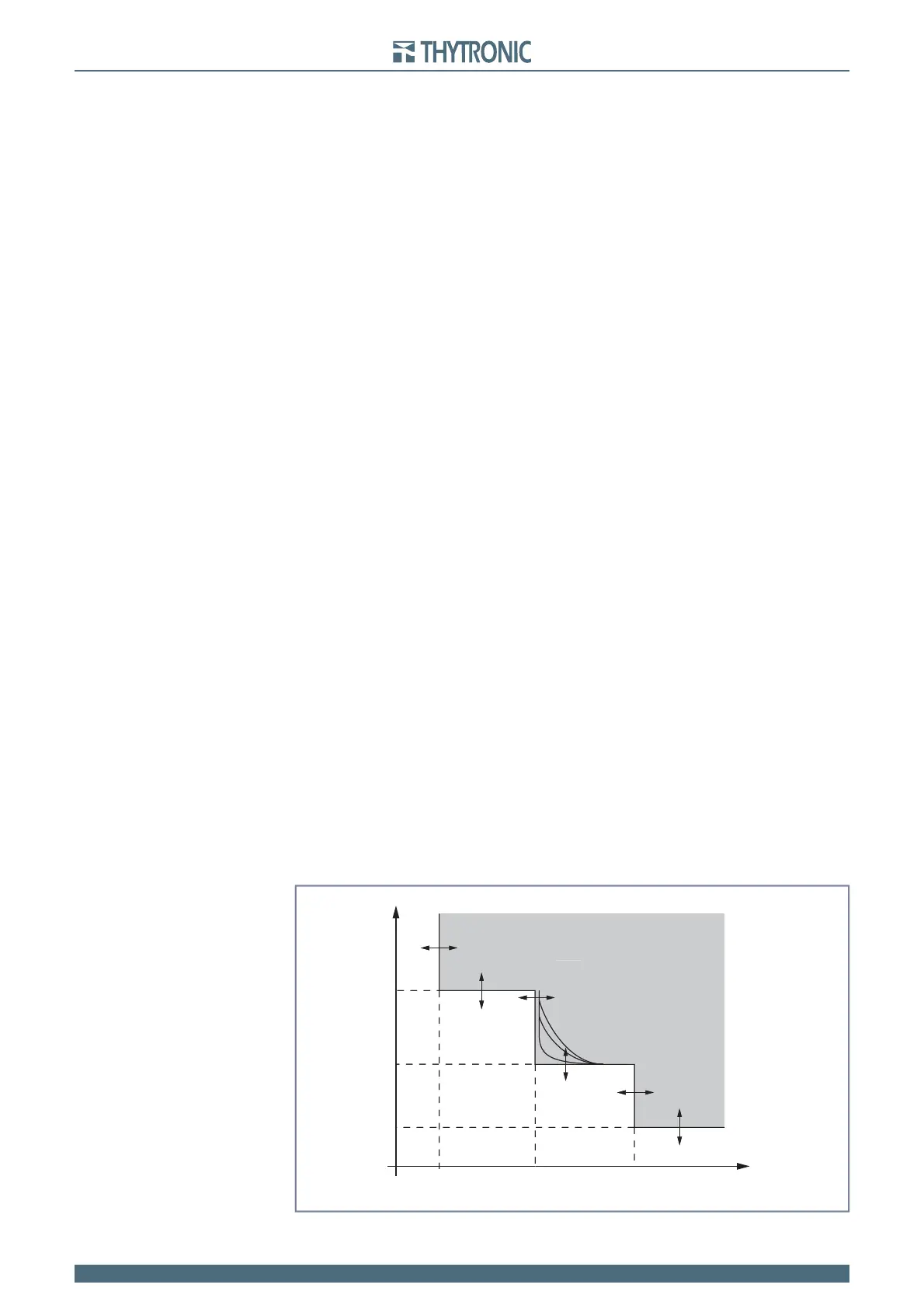
t-int-F46N.ai
I
NC
I
N
> I
N
>>
t
N
>
AL
t
N
>
t
N
>>
I
N
>
AL
t
TRIP
General operation time characteristic for the neutral unbalance elements - 46N
t-int-F46N.ai
I
NC
I
N
> I
N
>>
t
N
>
AL
t
N
>
t
N
>>
I
N
>
AL
t
RIPTRIP
General operation time characteristic for the neutral unbalance elements - 46N